161
AT6020
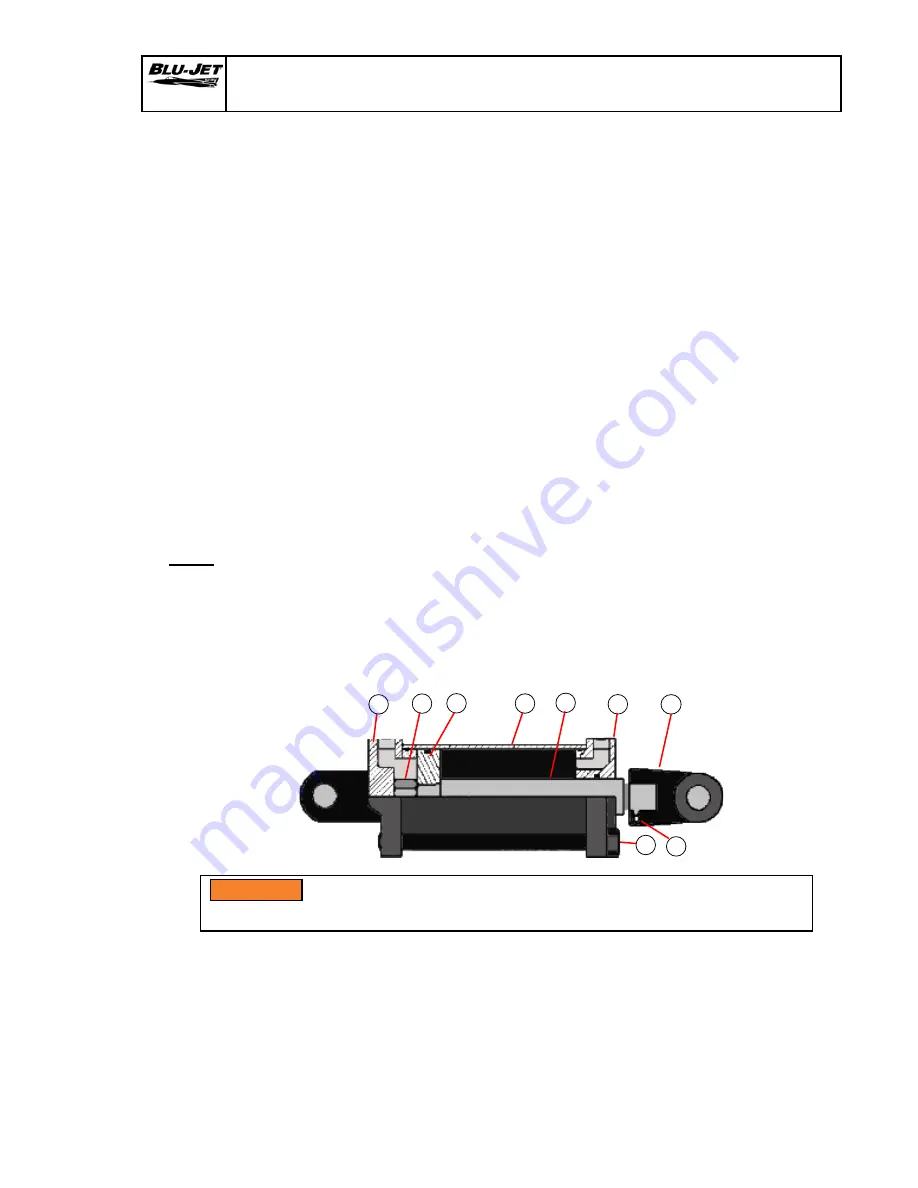
Tie-rod Cylinder Disassembly - Assembly Procedure
With cylinder removed from machine, clean, drained of oil and fully retracted, proceed as follows:
Disassembly:
1. Secure cylinder in vice or other method to prevent rotation. With the immediate area clean of
dirt so parts can be laid out.
2. Remove tie-rod nuts, item (1).
3. Pull rod assembly from cylinder. Remove tube, item (3).
4. Loosen nut item (4), and remove clevis, item (5), from rod assembly.
5. Place rod assembly in vice with copper or brass jaws so as not to damage.
6. Remove all seals from items (6), (8), and (9) for replacement. Clean and inspect all parts, for damage
(nicks, scratches, cracks and etc.) replace as necessary. If you have any question please contact
Prince Hydraulics (712) 235-1220.
Reassembly:
1. Replace all seals in items (6), (8), and (9). Do not replace small O-ring on ID of piston, item (8), until
ready to attach rod, item (2).
2. Place small ID O-ring seal for piston over rod turndown and apply light coat of grease to seal.
Slip piston, item (8), onto turndown with ID counter bore towards rod shoulder. Take care not to
pinch O-ring between piston and rod shoulder. Replace nut, item (7), and secure.
3. Apply light coat of grease to seals in gland, item (6), and slip gland over rod end, carefully so as
not to damage seals. Slip entire assembly into lightly oiled tube, item (3), piston first. Insure tube
slips up over OD seals of gland.
4. Take total assembly in step 3 and slip tube over OD seal on butt, item (9). Align ports in butt and
gland and apply nuts, item (1), to tie-rods and toque uniformly.
Tierod
3/8” tierods 20-23 ft./lbs. (27-31 Nm)
1/2” tierods 45-52 ft./lbs. (61-70 Nm)
5/8” tierods 95-105 ft./lbs. (129-142 Nm)
3/4” tierods 150-165 ft./lbs (203-224 Nm)
5. Test for leaks and reinstall in machine. If you have any problems contact Prince Hydraulics
(712) 235-1220.
6. The hydraulic system MUST have the air removed from the system after initial machine
set-up or following the repair or replacement of any part of the system.
7. Connect implement to the tractor drawbar correctly before operating or making any
adjustments.
1
9
8
3
2
6
5
4
7
WARNING:
Make sure you perform the required service and adjustments
correctly. Failure will damage machine or injure operator.
WARNING
Summary of Contents for AT6020
Page 12: ...10 AT6020 Safety Decals AP2973 AP2975 AP2974 AP2227 AP2972...
Page 23: ...21 AT6020 Safety Decals AP2973 AP2975 AP2974 AP2227 AP2972...
Page 46: ...44 AT6020 Center Section Area of Bundle 66000103 Depth Control Parts...
Page 59: ...57 AT6020 AT6020 48 and 60 Toolbars AT6020 48 AT6020 60...
Page 66: ...64 AT6020 AT6020 48 Hydraulics...
Page 67: ...65 AT6020 AT6020 48 Hydraulics Right hand From The Rear Left hand From The Rear...
Page 69: ...67 AT6020 AT6020 48 Hydraulics...
Page 70: ...68 AT6020 AT6020 48 Hydraulics Right hand From The Rear...
Page 71: ...69 AT6020 AT6020 48 Hydraulics Left hand From The Rear...
Page 72: ...70 AT6020 Bundle Number 66000108 Left Side Third Wing Left Side Bundle 66000108 8 22...
Page 74: ...72 AT6020 Bundle Number 66000108 Right Side Third Wing Right Side Bundle 66000108 2a 2a...
Page 82: ...80 AT6020 Auto Lok Nurse Tank Hitch AAM2931 Parts...
Page 100: ...98 AT6020 SuperShooter III Parts AAM3514...
Page 104: ...102 AT6020 SuperShooter III Add on Parts Dual Assembly 66000137 and 66000136...
Page 152: ...150 AT6020 Lighting Kit Slow Moving Vehicle Kit...
Page 154: ...152 AT6020 B Lighting Kit SMV Kit 20 Row Spacing...
Page 166: ...164 AT6020 Notes...
Page 219: ...217 Task Procedures Illustrations AT6020 AT6020 60...
Page 222: ...Task Procedures Illustrations 220 AT6020 AT6020 48 Hydraulics...
Page 230: ...Task Procedures Illustrations 228 AT6020 AT6020 48 Hydraulic Hose Installation...
Page 261: ...259 Task Procedures Illustrations AT6020 Lighting Kit 20 Row Spacing...
Page 262: ...Task Procedures Illustrations 260 AT6020 B Lighting Kit 20 Row Spacing...
Page 282: ...Task Procedures Illustrations 280 AT6020 Lighting Kit SMV Kit 20 Row Spacing...


