


18 AQT8-QAM/IP
User Manual
6.1 Accessing the Unit via a Web Browser
You must complete the steps described in Section 5 before proceeding as follows:
(1)
Open a web browser on your computer (Internet Explorer 7 or higher is recommended) and enter the following URL
address
(http://172.16.70.1)
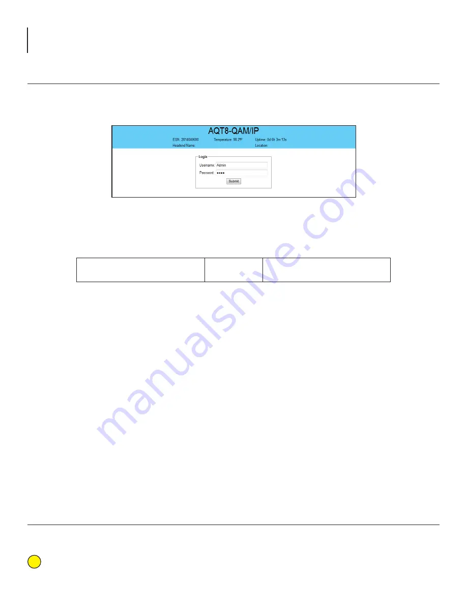
. The "Login" Screen (Figure 6.1) will appear.
(2)
Enter the following case-sensitive factory-default Username and Password, and click on the "Submit" button.
NOTE:
When logged in as Admin, the user has read and write permission. Only one Admin can be logged in at a time.
When logged in as Guest, the user has only read permission. Up to four Guests can be logged in simultaneously.
Username =
Admin
(case-sensitive)
Password =
pass
(case-sensitive)
- OR -
Username =
Guest
(case-sensitive)
Password =
pass
(case-sensitive)
Monitoring and configuration of the unit is achieved via a series of web pages as described in the Sections below. The
following read-only information is displayed in a “page header” – in blue color – on top of each web page:
ESN:
unit’s Serial number
Headend name:
a user-defined field to make identification easier
Temperature:
temperature of unit’s chipset.
Uptime:
time elapsed since last time the unit was turned on
Location:
a user-defined field to make identification easier
As shown in Figure 6.2, under the blue “page header” the following Primary tabs will appear:
• Primary tab
“Main”
includes the following sub-tabs: Status, Input Map, MPTS Output Config, IP Output Config,
Output, QAM, EAS, and Refresh
• Primary tab
“Network”
doesn’t include any sub-tab.
• Primary tab
“Time”
doesn’t include any sub-tab.
• Primary tab
“Event Log”
doesn’t include any sub-tab.
• Primary tab
“Logout”
doesn’t include any sub-tab.
• Primary tab
“Admin”
doesn’t include any sub-tab.
Each Primary and sub-tab is described in the subsequent Sections.
Section 6 – Configuring the Unit
Page
Header
{
Figure 6.1 - "Login" Screen
6.2 "Main > Status" Screen
The “Main > Status” screen (Figure 6.2) is a “read-only” screen and displays input and output information on each of the
eight (8) channels.
Input:
indicates the physical RF input and Transport Stream (TS) status. If background is red, there is no TS detected
or TS invalid.
1


