4
INSTALLATION
Installation Instructions
PLUMBING CONNECTIONS
WARNING
Plumbing connections must comply with ap-
plicable sanitary, safety and plumbing codes.
The water supply inlets are provided with 3/8” (10 mm)
compression fittings for 3/8” O.D. copper tubing. The wa
-
ter supply line pressure should be 25 - 50 psi (170 - 345
kPa) for each line. The water supply to the generator tank
is separate from the water supply to the cooling system
where steam is condensed before entering the drain line.
Install line strainers (not provided). A manual shutoff valve
for each supply line must be provided convenient to the
steamer.
Treated water feeding the boiler inlet supply is recom-
mended, and untreated water feeding the condensing
water inlet. Hook-ups are labelled on the back of the
steamer.
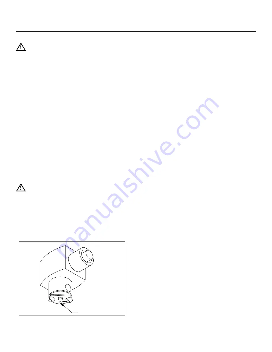
10 pan units are provided with an adjustable condensing
water valve. It has been factory set to 2-1/2 turns open,
that will suit most installations. Adjust as required to suit
local water inlet temperature and pressure. Turn screw
clockwise to decrease flow or counterclockwise to in
-
crease flow.
DRAIN CONNECTIONS
CAUTION
In order to avoid any back pressure in the
steamer, do not connect solidly to any drain
connection.
The drain connection must be 1½” IPS down, preferably
with one elbow only, maximum length of 2 feet horizontal
before open air gap and piped to an open air gap type
drain. Drain pipe should be copper. DO NOT use PVC
pipe - PVC pipe may lose its rigidity or glue may fail.
Adjusting Screw
Figure 3
WATER QUALITY
The water supply connected to this steamer should con-
tain no more than 2.0 grains of hardness per gallon with
pH from 7.0 to 8.5. This degree of hardness and pH can
easily be obtained with the use of a properly maintained
water softener.
Water supplies vary from one location to another. A local
water treatment specialist should be consulted before in-
stalling any steam generating equipment.
Untreated water contains scale producing minerals which
can precipitate onto the surfaces in the boiler. Due to the
temperatures in the boiler, the minerals can bake onto the
surfaces and components. This can result in early compo-
nent failure and reduced product life.
Mineral scale on components causes several problems:
1. The surfaces of the heating devices become coated
with scale, reducing the heat transfer efficiency. This
can produce hot spots on the heating elements and
result in premature failure.
2. The water level probes become coated with scale.
Scale will bridge across the probe insulator from the
metal extension which senses the water level in the
boiler cell. Once this scale becomes wet, the water
level control is unable to maintain the proper water
level in the boiler. This situation may cause an electric
heating element to fail if the element is not adequate-
ly covered by water.
Strainers and filters will NOT remove minerals from the
water.
Refer to REMOVAL OF LIME SCALE DEPOSITS, in this
manual.


