User Manual
Publication date: March, 2006
Revision A2
32
•
The Information of Page Layout
⎯
On the top side, it shows the front panel of the switch. In the front panel, the
linked ports will display green; as to the ports, which are link off, they will be
dark. For the optional modules, the slot will show only a cover plate if no
module exists and will show a module if a module is present. The image of
module depends on the one you inserted. The same, if disconnected, the port
will show just dark, if linked, green.
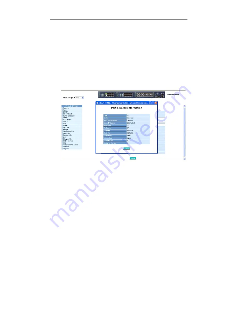
In this device, there are clicking functions on the panel provided for the
information of the ports and the TP/fiber in 3 module slots. These are very
convenient functions for browsing the information of a single port or TP/fiber
module. When clicking the port or the edge of TP/fiber module on the front
panel, an information window for them will be pop out. (See Fig. 3-3~3-4)
Fig. 3-3 port detail information
In Fig. 3-3, it shows the basic information of the clicked port. With this, you’ll
see the information about the port status, traffic status and bandwidth rating for
egress and ingress respectively.
Summary of Contents for 3-Slot 24 Fast Ethernet + 2 Gigabit L2 Managed Switch with Redundant Power
Page 6: ...vi ...
Page 8: ......
Page 157: ...User Manual Publication date March 2006 Revision A2 149 Fig 4 1 Fig 4 2 ...
Page 254: ......
Page 255: ......


