background image

Page 11

724-746-5500   |   blackbox.com


Chapter 3: Components

3.2 Housing with Radio, Power Supply, Heater, and Blower Installed

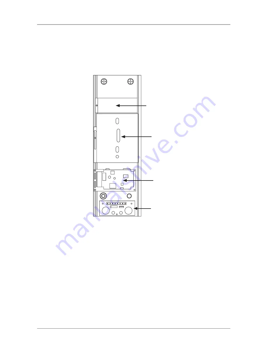
The radio arrives already installed in the tube housing. Figure 3-2 shows the 

tube housing with radio installed.

Heater

Camera goes here 

(not installed yet)

Radio board

Power board (blower 

is underneath power 

board)

Figure 3-2. Housing configuration as shipped. 

3.3 Tube Camera (Ordered Separately) with Housing

The camera (not included) installs in the tube housing. Figure 4-1 shows the 

tube housing with camera installed.

3.4 Overview of Products Combined

Figure 2-1 shows the complete system with all components installed.

Summary of Contents for LS900A

Page 1: ...ckbox com About Black Box Black Box Network Services is your source for more than 118 000 networking and infrastructure products You ll find everything from cabinets and racks and power and surge protection products to media converters and Ethernet switches all supported by free live 24 7 Tech support available in 20 seconds or less Copyright 2009 All rights reserved ...

Page 2: ...njector Works with Sony IPELA Fixed IP Camera SNC CS50 ordered separately LongSpan 900 MHz Wireless Ethernet Tube Housing Kit Order toll free in the U S Call 877 877 BBOX outside U S call 724 746 5500 FREE technical support 24 hours a day 7 days a week Call 724 746 5500 or fax 724 746 0746 Mailing address Black Box Corporation 1000 Park Drive Lawrence PA 15055 1018 Web site www blackbox com E mail...

Page 3: ...necessary to correct the interference Changes or modifications not expressly approved by the party responsible for compliance could void the user s authority to operate the equipment This digital apparatus does not exceed the Class A limits for radio noise emis sion from digital apparatus set out in the Radio Interference Regulation of Industry Canada Le présent appareil numérique n émet pas de br...

Page 4: ...r en libreros o gabinetes que impidan el flujo de aire por los orificios de ventilación 10 El equipo eléctrico deber ser situado fuera del alcance de fuentes de calor como radiadores registros de calor estufas u otros aparatos incluyendo amplificadores que producen calor 11 El aparato eléctrico deberá ser connectado a una fuente de poder sólo del tipo descrito en el instructivo de operación o como...

Page 5: ...ación 18 Servicio por personal calificado deberá ser provisto cuando A El cable de poder o el contacto ha sido dañado u B Objectos han caído o líquido ha sido derramado dentro del aparato o C El aparato ha sido expuesto a la lluvia o D El aparato parece no operar normalmente o muestra un cambio en su desempeño o E El aparato ha sido tirado o su cubierta ha sido dañada ...

Page 6: ... trademarks of BB Technologies Inc Mac is a registered trademark of Apple Computer Inc Linux is a registered trademark of Linus Torvalds Microsoft and Windows are registered trademarks of Microsoft Corporation Wi Fi is a registered trademark of the Wi Fi Alliance Any other trademarks mentioned in this manual are acknowledged to be the property of the trademark owners ...

Page 7: ... with Housing 11 3 4 Overview of Products Combined 11 4 Installation 12 4 1 Connecting the Radio and Power Supply 12 4 2 Installing the Housing 13 4 3 Installing a Sony SNC CS50 Camera Not Included into the Housing 13 4 4 Wiring 15 4 5 Mounting the Housing 17 4 6 Connecting the Standalone Radio or Radios 19 5 Configuring the Radio 20 5 1 Digital Setup 20 5 2 Physical Setup 24 6 Installing and Adju...

Page 8: ...h Radio Link Budget LS900A 148 dB with 15 dBi antenna Receive Sensitivity LS900A 97 dBm at 10e 4 BER 112 dBm with 15 dBi antenna Speed LS900A RF Transmission Rate 1 536 Mbps Ethernet Throughput 935 kbps Connectors LS900A 1 RJ 45 PoE 10BASE T 100BASE TX Indicators LS900A LEDs 1 Power 1 Ethernet Link 1 RF RX 1 RF TX 4 Channel 6 Link Quality Power LS900A LS900PKA From 110 VAC 60 Hz external power ada...

Page 9: ...ow each component of the system operates When you receive your kit the radio circuit board heater blower and power supply are already installed in the tube housing You will need to install the camera ordered separately yourself complete instructions appear in Section 4 3 of this manual 2 2 What s Included Your package should include the following items If anything is missing or damaged please cont...

Page 10: ...sion Next it s thermally sustainable at high temperatures And since it s a virtual Ethernet connection you don t have the hassle of installing a large wiring infrastructure A LongSpan wireless Ethernet uplink runs at a speed of up to 1 Mbps If you don t think that is fast enough for low data rate applications just consider that the uplink speed on a typical DSL line is 38 4 kbps well within the 1 ...

Page 11: ...wer to back of camera Camera sled Antenna 24 VDC to 24 VAC power converter Power in Blower fan underneath power board Power board on top Radio board Heater Power cable Antenna RF TNC connector Power and data CAT5e cable outdoor grade 300 ft 50 m maximum Power over Ethernet injector 10BASE T data cable 110 VAC power plug Wireless radio Figure 2 1 Application ...

Page 12: ...Kit components are illustrated below 3 1 Radio Extender The radio extender board installed in the tube housing is our LS900A It oper ates the same as the standlone model see Chapter 5 Figure 3 1 shows the radio board RJ 45 network connector links radio board to camera Power connector Radio board Figure 3 1 Close up of radio board with cable connections ...

Page 13: ...radio installed Heater Camera goes here not installed yet Radio board Power board blower is underneath power board Figure 3 2 Housing configuration as shipped 3 3 Tube Camera Ordered Separately with Housing The camera not included installs in the tube housing Figure 4 1 shows the tube housing with camera installed 3 4 Overview of Products Combined Figure 2 1 shows the complete system with all comp...

Page 14: ...ube housing Power to back of camera Camera sled Antenna 24 VDC to 24 VAC power converter Power in Blower fan underneath power board Power board on top Radio board Heater Power cable Figure 4 1 Installation diagram side view You will need to make a few simple connections between the components 1 Connect one end of the Ethernet cable to the radio board 2 Connect one end of the power cable to the rad...

Page 15: ...ief plug from the inside of the housing and tighten Repeat for the other plug OPTION Omit one or both cable strain relief plugs if 1 2 metal conduit is used in the cable entry holes 4 3 Installing a Sony SNC CS50 Camera Not Included into the Housing 1 To loosen the camera sled turn the panhead screw located on the inside ledge of the bottom half of the housing 1 2 turn counterclockwise Slide the c...

Page 16: ...o that it is parallel with the sled and tighten bolt 3 Place the sled leg of the completed camera sled assembly into the channel on the bottom of the housing Adjust the camera sled until the key slot hole aligns with the panhead screw Make sure the camera is seated properly Slide the camera sled forward to the desired position Tighten the screw to secure the camera Sled screw Camera sled Camera Ca...

Page 17: ...ousing Make wiring connections to the camera and lens as required by the manufacturer Camera installed Power connector Power board with wires connected RJ 45 network connector links radio board to camera Radio board Figure 4 4 Wiring connections 2 Turn the cable strain reliefs to tighen down on the wiring cable WARNING A readily accessible disconnect device should be incorporated in the fixed wiri...

Page 18: ...24 VAC wiring distances Wire Gauge 22 20 28 16 14 12 10 Total VA 35 44 70 112 179 285 452 Consumed 1 Run 24 VAC power through a cable strain relief separate from the Ethernet Place stripped power wire ends into the power board terminals marked 24 AC in 2 Secure the ground wire to the screw located in the bottom rear of housing 3 Tighten the terminal block screws then tighten the cable strain relie...

Page 19: ...cation on the pole See Figure 4 6 Figure 4 6 Positioning the bracket on a pole 2 Attach the assembly to the pole using 3 4 mounting straps not included 3 Slide the mounting straps through the slots in the bracket and tighten to the pole see Figure 4 7 Figure 4 7 Securing the bracket to the pole with mounting straps Bracket Pole Mounting straps Bracket Pole ...

Page 20: ... mark the bracket mounting pattern Using the appropriate hardware and methods secure the bracket to the wall 3 After securing the bracket to the wall take the camera housing and align the tilt mechanism Insert the 1 4 20 x 5 8 bolts into the holes and finger tighten Figure 4 8 Aligning the housing s tilt mechanism 4 Adjust the camera to the desired position and tighten the bolts to prevent camera ...

Page 21: ... Ethernet injector 10BASE T data cable Ethernet RJ 45 connector 110 VAC power plug Wireless radio Antenna Figure 4 10 Installing the standalone radio Included at the other end of the wireless Ethernet link 1 Using CAT5e cable connect the power injector included to the radio 2 Using an RJ 45 CAT5e cable attach the other end of the power injector to the Ethernet network Then connect the power plug t...

Page 22: ...you to either Run or Save the application Press Run to start it immediately press Save to save the application before running NOTE This utility only runs on Microsoft Windows not Linux or Mac If you must use a non Windows computer for configuration make sure your subnet mask allows your computer to see 192 168 1 17 Connect to that default IP address with your Web browser continuing the setup proce...

Page 23: ...io IP Configuration screen The information on the left in Figure 5 2 is the current status of the radio the boxes on the right allow you to change it Make sure that the radio s IP address is in the same subnet as your computer For example if the subnet mask is 255 255 255 0 a class C network the first three number groups of the IP address must match Choose your desired parameters and click Apply 5...

Page 24: ...age has sections similar to the login page showing radio statistics and device information plus it adds several new sections The Device Settings section allows you to set the network information and choose an RF frequency channel The default is to allow the radio to choose its own frequency based on minimizing interference If you set a fixed channel make sure the AP and all SUs use the same one Re...

Page 25: ...with a warning that it s for advanced users only Despite the warning you will need to click the Advanced Admin button to set the device type ID and encryption key You will then see a page similar to Figure 5 4 Figure 5 4 Advanced admin page 8 On the Advanced Admin page set the parameters as follows Choose Device Type Access Point or Subscriber Unit For an AP enter the number of SUs that will be co...

Page 26: ...io securely Maximize lightning resistance by providing a strong DC ground connection to the metal housing 3 Connect the radio s TNC RF connector to a suitable antenna A simple omni directional dipole unit is included you can use this antenna for testing and for relatively undemanding applications If your application requires greater distance and or a wider range of direction choose either the Long...

Page 27: ...ou install your wireless antenna follow a few basic rules All antennas have a polarity The antenna could have horizontal polarity or vertical polarity Figure 6 1 illustrates the difference between the two polarizations with a 2 5 dBi antenna and an 11 dBi antenna Vertical polarization 2 5 dBi antenna 11 dBi antenna Tube housing Horizontal polarization 2 5 dBi antenna Tube housing 11 dBi antenna Fi...

Page 28: ...l project out from the sides of the antennas The radio wave patterns will resemble a doughnut Because of this pattern never try to point the ends of the antennas directly toward one another or directly away from one another WRONG Do not aim the 2 5 dBi antennas directly at each other RIGHT RIGHT Figure 6 2 Antenna diagram 2 2 5 dBi omnidirectional antenna 2 5 dBi omnidirectional antenna 2 5 dBi om...

Page 29: ...rectly out the front of the antenna Because of this you should always point the 11 dBi antennas direcly at each other and never point them away from each other For a maximum range point to point one unit we recommend using the auto channel selection mode and a maximum gain of 11 dBi 2 5 dBi omnidirectional antenna 2 5 dBi omnidirectional antenna 2 5 dBi omnidirectional antenna 2 5 dBi omnidirectio...

Page 30: ...x com LongSpan 900 MHz Wireless Ethernet Tube Housing Kit RIGHT RIGHT WRONG WRONG Figure 6 4 Antenna diagram 4 11 dBi antenna 11 dBi antenna 11 dBi antenna 11 dBi antenna 11 dBi antenna 11 dBi antenna 11 dBi antenna 11 dBi antenna ...

Page 31: ...LED is not lit Solution Check your network connections A 2 Calling Black Box If you determine that your Long Span Tube Housing Kit is malfunctioning do not attempt to alter or repair the unit It contains no user serviceable parts Contact Black Box Technical Support at 724 746 5500 Before you do make a record of the history of the problem We will be able to provide more efficient and accurate assis...

Reviews: