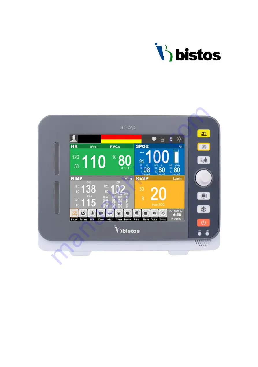
BT-740 Patient monitor
Operation Manual
Keep this manual for future reference
P/N : 740-ENG-OPM-EUR-D03
Page 1: ...BT 740 Patient monitor Operation Manual Keep this manual for future reference P N 740 ENG OPM EUR D03...
Page 2: ...er no responsibility is assumed by Bistos for its use or any infringements of patents or other rights of third parties that may result from its use No license is granted by implication or otherwise un...
Page 3: ...8 Essential performance 28 2 Preparing for operation 29 2 1 Installation 29 2 2 Connecting to power 31 3 Basic operations 32 3 1 Turn on 32 3 2 Turn off 33 3 3 Basic operations 33 3 4 Operation mode 3...
Page 4: ...play 70 8 5 Respiration setup 71 8 6 Alarm setup 72 9 PR 73 9 1 Overview 73 9 2 Display 73 9 3 Setting PR sound 73 9 4 Alarm setup 73 10 SpO2 74 10 1 Overview 74 10 2 Safety information 75 10 3 Monito...
Page 5: ...cleaning 97 15 1 Overview 97 15 2 Cleaning 97 15 3 Disinfection 98 16 Maintenance 99 16 1 Checking 99 16 2 Viewing software version information 100 16 3 Maintenance plan 100 16 4 ECG calibration 100 1...
Page 6: ...Lead full screen format 48 Figure 7 1 3 Lead placement method 62 Figure 7 2 5 Lead placement method 63 Figure 7 3 ECG wave in standard display format 65 Figure 7 4 ECG parameter in standard display f...
Page 7: ...nd this manual in order to stand for the information about Used to identify safety information Be well known this information thoroughly before using BT 740 Used to identify safety information Be well...
Page 8: ...tes a defibrillation proof type CF applied part Indicates CLASS II equipment Adapter Indicates the date after which the medical device is not to be used Indicates to keep the device dry Indicates the...
Page 9: ...es the device contains natural rubber latex Accessories Indicates the packing material is recyclable Indicates to not dispose the device together with unsorted municipal waste for EU only The solid ba...
Page 10: ...schedule it will result in device failure and may endanger the patient s safety Use the patient monitor under the conditions specified in this operation manual Beyond the conditions the patient monit...
Page 11: ...rument The physiological wave physiological parameters and alarm information displayed on the monitor are only for the doctor s reference and should not be directly used as the basis for clinical trea...
Page 12: ...l force Avoid instrument splashed by water Avoid high temperatures the instrument should be used within a temperature range of 5 40 Avoid using instrument in the environment such as pressure is too hi...
Page 13: ...ed in such a case Any non medical equipment such as the external printer is not allowed to be used within the patient vicinity 1 5m 6ft Parts and accessories used must meet the requirements of the app...
Page 14: ...tive dust or dirt Do not allow cleaning agents to contact electrical components and do not spray cleaning solutions onto any of these surfaces Personal injury or equipment damage could occur Do not ex...
Page 15: ...ecting the battery with polarity Do not use the battery near fire or environmental temperature exceeds 60 Do not heat or splash the battery or throw it into fire or water Do not destroy the battery Do...
Page 16: ...s from 5 40 Operating humidity ranges from 30 85 Avoid in the vicinity of electric heater Avoid placing in an area where there is an excessive humidity rise or ventilation problem Avoid placing in an...
Page 17: ...nt monitors are intended to be used only under regular supervision of clinical personnel It is suitable for adult and pediatric The intended locations of use are hospitals and clinics 1 Intended patie...
Page 18: ...pressure NIBP Indication To determine a patient s blood pressure Screen for hypertension Following the effect of anti hypertensive treatments in a patient to optimize their management Assessing a per...
Page 19: ...therapy as the evaluation of primary and secondary cardiomyopathic processes among others Contraindications No absolute contraindications to performing an ECG exist other than patient refusal Some pat...
Page 20: ...tem configurations Basic configuration of BT 740 Main body with 8 touch screen and built in lithium ion battery ECG cable and electrode Adult SpO2 probe and extension cable Non invasive blood pressure...
Page 21: ...for ECG measurement 1ea Adult SpO2 sensor standard SpO2 sensor for adult 1ea SpO2 extension cord Standard Cord to connect the SpO2 sensor and main body 1ea Adult NIBP cuff standard Measures NIBP for a...
Page 22: ...BT 740 Operation manual 21 P N 740 ENG OPM EUR D03 Bistos Co Ltd 2018 05 1 4 Product outlook Figure1 1 Front view Figure1 2 Side view...
Page 23: ...BT 740 Operation manual 22 P N 740 ENG OPM EUR D03 Bistos Co Ltd 2018 05 Figure1 3 Rear view...
Page 24: ...easured value 3 Power Power On Press down the key more than 2 seconds Power Off Press down the keys more than 2 seconds and the system will display the alarm message The system will shut down 3 second...
Page 25: ...the cursor Press select the menu or execute a command 10 Setting Enter to the setting mode Press again to close the setting mode 11 Freeze Freeze unfreeze the waveform 12 Speaker holes For alarm and...
Page 26: ...1 6 Rear view Name Description 1 Battery cover Battery compartment cover 2 Handle Handle for main body transport 3 Bracket To wall mount the monitor 4 Air intake For ventilation 5 Auxiliary output int...
Page 27: ...arameter on the left side 3 Parameter area Show the corresponding parameter measured value and current upper and lower alarm limits of each parameter module The parameters are shown in fixed position...
Page 28: ...monitor and enable the user to use specific features conveniently Key Name Description Pause Alarm pause Pat Set Patient information setting NIBP NIBP measurement start and stop Event Manual event ma...
Page 29: ...ensors to the appropriate site of patient The device is composed with display control circuit and panel and input part for various sensors It detects ECG SpO2 NIBP etc using ECG cable and specific pro...
Page 30: ...organization or individual shall not interpolate copy or exchange by any means or form When the monitor is combined with other devices it must comply with IEC 60601 1 2005 A1 2012 and should not be co...
Page 31: ...uring transport Storage The packaged monitor should be stored in well ventilated room with ambient temperature 20 60 relative humidity 0 95 Non condensing atmospheric pressure 700 1060 mbar hPa and wi...
Page 32: ...ot disconnect any cable Connect to power adapter in the following steps Make sure that the AC power supply meets the following specifications a c 100V 240V 50 60Hz Use the power adapter provided with...
Page 33: ...tely 3 1 2 Start the monitor If finish to check the monitor it is ready to start the monitor Press the Power key the yellow warning lights flash once and the system enter the program reading interface...
Page 34: ...and hold the Power key for 2 seconds to pop up the 3 seconds countdown window and the monitor turns off in 3 seconds CAUTION If the monitor is not turned off properly you can simply disconnect the pow...
Page 35: ...eys The physical keys on the monitor such as the Alarm pause key on the front panel Popup keys Menu keys relevant to the tasks that automatically appear on the monitor screen when need such as the con...
Page 36: ...on can enter the corresponding submenu Confirmation key area Some menus contain a confirmation key area to confirm the menu operations including confirmation and cancel key 3 4 Operation mode The moni...
Page 37: ...delaying diagnosis and treatment 3 5 Measurement setup This section only describes the general settings of measuring wave in monitor mode for other specific settings of each parameter please refer to...
Page 38: ...nu Select Device Name Enter device name through the soft keyboard on the screen Select Department Enter the sector and department using the device through the soft keyboard on the screen Select Bed Nu...
Page 39: ...YYYY MM DD Set the year month and day Time 24H Set the hour minute and second Select Date Format and set the date format in accordance with custom YYYY MM DD Year Month Day MM DD YYYY Month Day Year D...
Page 40: ...a preferred unit through the following operations Select Settings Smart Hotkey or press Setting key on the monitor panel Settings Select User Maintenance enter the password and confirm User Maintenan...
Page 41: ...Patient Type and Pace Maker Patient Type default Adult Pace Maker default No and the user must confirm that the default value is appropriate for the patient being monitored For patients with pacemake...
Page 42: ...mit Warning message OK Quick Admit menu as shown in Figure 4 2 Figure 4 2 Quick Admit menu Select Patient Type and set the patient category as needed Adult and Pediatric Select Pace Maker and set whet...
Page 43: ...Letters not more than 20 characters 2 Select First Name and enter patient name through the soft keyboard Letters not more than 20 characters 3 Select Patient ID and enter the patient ID through the so...
Page 44: ...tient menu select Discharge Patient Warning message OK to finish the operation of discharging a patient After the patient is discharged all the information of the patient stored in the monitor will be...
Page 45: ...To clear NIBP trend operate as follows In the Patient menu select Clear NIBP Trend Warning message OK to finish the operation of clear NIBP trend After the NIBP trend was cleared all the information o...
Page 46: ...reen The user can select the display format according to needs and get different screen information 5 1 Selecting user interface Select the user interface as follows Select Displays smart hotkey Scree...
Page 47: ...format Figure 5 1 Standard Display The normal display provides the parameter wave being monitored and the parameters displayed in the parameter area This is the basic display of the monitor In this di...
Page 48: ...740 ENG OPM EUR D03 Bistos Co Ltd 2018 05 5 2 2 Big ECG format The big ECG format is as shown in Figure 5 2 Figure 5 2 Big ECG format 5 2 3 Big font format The big font format is as shown in Figure 5...
Page 49: ...0 Operation manual 48 P N 740 ENG OPM EUR D03 Bistos Co Ltd 2018 05 5 2 4 ECG 7 Lead full screen format The ECG 7 Lead full screen format is as shown in Figure 5 4 Figure 5 4 ECG 7 Lead full screen fo...
Page 50: ...alarms technical alarms and prompt messages Physiological alarms A physiological alarm is usually triggered when a physiological parameter of the patient exceeds the alarm limit or the patient has phy...
Page 51: ...danger the patient s life the mechanical failure or disoperation of the monitor will affect the normal monitoring of key physiological parameters Low priority alarms The patient s physiological signs...
Page 52: ...tics when an alarm occurs High priority alarm Beep beep beep beep beep beep beep beep beep beep Medium priority alarm Beep beep beep Low priority alarm Beep 6 3 3 Alarm information Alarm information d...
Page 53: ...e alarm modes you can also set the monitor to the following three alarm states as needed and display different alarm icons on the screen Alarm Reset Alarm sound off Alarm pause Alarm off 6 4 1 Alarm r...
Page 54: ...is on the system will have alarm reminder tone 6 4 3 Alarm pause Press the Pause smart hotkey or Alarm pause key on the monitor panel to temporarily stop the alarm of the monitor in the following ste...
Page 55: ...alarm prompt characteristics maintained in alarm pause state Pause smart hotkey will appear magnified icon The physiological alarm area displays Alarm Pause You can press the Pause smart hotkey again...
Page 56: ...min 2 min or 3 min By default the ST alarm delay time is 20 seconds 6 5 2 Setting the alarm reminder signal and alarm reminder interval The alarm reminder signal can be turned on or off When the alar...
Page 57: ...s follows Mid Set the alarm priority to medium High Set the alarm priority to high Note Regulatory requirements the parameter ECG blood oxygen saturation blood pressure can set the alarm priority high...
Page 58: ...ystem will still be latched that is continue to display the alarm information corresponding to physiological alarm the alarm sound also continues but the alarm mode has the following changes Parameter...
Page 59: ...y record these events through the Event smart hotkey and then view it in the event review refer to15 4 Event Review for detailed operation 6 8 Alarm record When the monitor s machine alarm system is p...
Page 60: ...s connected to the monitor ECG electrodes connected to the patient Connect to the monitor with five lead ECG cable and ECG can display two different waves by adjusting the two leads You can use the co...
Page 61: ...nalysis must be turned on Otherwise the pacing pulse may be counted as a normal QRS wave make the ECG signal too weak to detect the alarm Periodically check the skin that the electrode is placed at If...
Page 62: ...ement to remove dead skin cells Wash the skin thoroughly with soap and water do not use ether and pure alcohol as this will increase the skin s impedance Dry the skin completely before placing the ele...
Page 63: ...ndard and American Standard European Standard EN American Standard AHA Lead Name Color Lead Name Color R Red RA White L Yellow LA Black F Green LL Red N Black RL Green C White V Brown 7 3 4 Installing...
Page 64: ...ulder N RL electrode placed on the right abdomen F LL electrode placed on the left abdomen C V electrode placed on the chest wall European Standard American Standard Figure 7 2 5 Lead placement method...
Page 65: ...the patient information area When the system detects a pacing signal the symbol will be marked in the top of the ECG wave You can change the pacing state in the following method Select the patient inf...
Page 66: ...for reference purposes only The graphics displayed on your monitor may be slightly different Figure 7 3 ECG wave in normal display format In addition when Pace Maker is set to Yes and the patient wea...
Page 67: ...nitoring as the HR source Select Calculated Channel and select heart rate calculated channel Auto Automatically select Heart Rate calculated Channel I Select the first ECG waveform as the Heart Rate c...
Page 68: ...is 25mm s Select Filter and set the filter mode Diagnostic Diagnostic mode Monitor Monitor mode Surgery Surgery mode Select Arrhythmia Analysis and set the alarm switch alarm level alarm record Select...
Page 69: ...easuring the changing impedance value The monitor calculates the respiration rate RR according to the wave cycle 8 2 Safety information NOTE Respiration monitoring does not apply to patient with large...
Page 70: ...rm and L left arm electrodes of I lead or R right arm and F left leg electrode of II lead NOTE For optimal respiration wave R and L electrodes should be placed horizontally if I lead is selected for r...
Page 71: ...used by rhythmic blood flow this will happen Placing the respiration electrodes correctly will reduce this effect The liver and ventricle should avoid the connection of respiration electrode so that t...
Page 72: ...priate value and set the apnea alarm time When the apnea time of the patient is longer than the set time the monitor will trigger an alarm Set time can be set 20s 25s 30s 35s 40s 45s 50s 55s 60s defau...
Page 73: ...LA RA LL LA RL and LL RL The default is RA LA 8 5 5 Setting sensitivity In RESP Setup menu select sensitivity and set the sensitivity The sensitivity is 1 2 3 4 5 The default is 2 8 5 6 Show The user...
Page 74: ...SpO2 parameter color of PR source as shown in Fig 9 1 Figure 9 1 PR parameter display 9 3 Setting PR sound Select SpO2 parameter area or SpO2 wave area SpO2 Setup menu Select Pulse Volume to set Puls...
Page 75: ...sion intensity through the tissue bed and calculate the concentration of hemoglobin and SpO2 The passing lights depend on a variety of factors most of which are constant However one of these factors t...
Page 76: ...nsor cable Avoid using the monitor and sensors while using the NMR equipment in order to avoid severe burns to the patient as a result of induced currents During long time continuous monitoring of a p...
Page 77: ...on the patient s body 5 Select the appropriate alarm settings 6 Start monitoring NOTE Turn on the monitor plug in SpO2 probe and connect patient s finger or toe monitor displays SpO2 wave SpO2 Pulse...
Page 78: ...ion manual 77 P N 740 ENG OPM EUR D03 Bistos Co Ltd 2018 05 10 4 Display SpO2 parameter area is as shown in figure 10 1 Figure 10 1 SpO2 parameter display SpO2 wave is as shown in figure 10 2 Figure 1...
Page 79: ...ting wave speed Select Wave Speed and set wave speed to 12 5mm s or 25mm s the faster speed the smoother wave 10 5 2 Setting wave mode Select Wave Mode and set the wave drawing mode Scan Scan mode Fil...
Page 80: ...moglobin COHb and methemoglobin MetHb Shock anemia hypothermia and the application of vasoconstrictor drugs may reduce the arterial blood flow to a level that cannot be measured The measurement also d...
Page 81: ...used to check the function of the monitor and can be used to assess the accuracy of the pulse rate but cannot be used to assess the accuracy of blood oxygen Functional testers cannot be used to evalua...
Page 82: ...pressure Manual mode Using Manual mode start to measures by hand Automatic mode measures Use manual mode to open automatic mode then the measure will automatically turn to automatic mode after a cert...
Page 83: ...the duct when the cuff is inflated and makes the infusion slow down or be blocked The inflatable tube connecting the blood pressure cuff and the monitor should be smooth without entanglement The pres...
Page 84: ...ythmia which results in irregular heartbeat the measurement will be unreliable and even cannot be done and the pressure measurement time will be extended Use of an artificial heart lung machine If a p...
Page 85: ...ressure cuff extension tube to the monitor 4 Select the cuff in accordance with the following method make sure that the cuff is completely deflated and then tie it to the upper arm or thigh of the pat...
Page 86: ...where he she can readily operate the sphygmomanometer 11 4 3 Start stop measurement Use the NIBP start stop key on the monitor panel or NIBP smart hotkey on the display to start stop the blood pressu...
Page 87: ...e patient is adult the pressure can be select from 140 160 180 The default cuff pressure value is 160 Select Initial pressure and set the appropriate cuff pressure value When the patient is pediatric...
Page 88: ...Rinsed with copious amounts of distilled water NOTE Please be especially careful to clean the air ball and control valve of whole air system Do not allow any liquid entering into reversing valve and s...
Page 89: ...Off and TEMP2 Sensor Off prompt and make an alarm sound Calibrate the temperature measuring instrument at least once every two years or according to hospital procedures When calibration is required pl...
Page 90: ...perature of two channels T1 and T2 and the alarm limits difference between the two temperature TD and temperature units Select Temp parameter area and open the Temp Setup menu Temperature display area...
Page 91: ...er area TEMP Setup menu In the TEMP Setup menu set Unit to or 12 7 Alarm setup In TEMP Setup menu select Alarm Setup to enter Alarm Setup interface and set TEMP alarm switch alarm level upper and lowe...
Page 92: ...following window Figure 13 1 Trend chart In the trend chart use the following method to select the parameter to be reviewed Select the parameter box rotate the shuttle to select the parameters to be r...
Page 93: ...key to enter Trend menu select Tabular and enter the following window Figure 13 2 Trend table Browse the trend table in the following method Select and to turn pages to left or right and move the tren...
Page 94: ...indow Figure 13 3 NIBP measurement review This window shows the measurement time of noninvasive blood pressure systolic blood pressure SYS diastolic blood pressure DIA mean blood pressure MAP and puls...
Page 95: ...the battery to power the monitor to avoid interrupting the monitor working The battery icon on the screen indicates the battery status Battery is working properly and is fully charged Battery is work...
Page 96: ...e servicing the monitor or you suspect that the battery is the fault source also check the battery performance WARNING Keep the battery out of the reach of children Use only the designated battery If...
Page 97: ...time stated in specifications please contact our service personnel for replacing the battery WARNING Do not open the battery compartment Only the qualified service personnel authorized by the manufac...
Page 98: ...ency of cleaning Before cleaning please consult the hospital about device cleaning requirements Below are available cleaning agents Diluted ammonia Diluted sodium hypochlorite washing bleach Diluted f...
Page 99: ...any part of the device into liquid Do not leave any cleaning solution on the surface of any part of the device NOTE Wipe the monitor and sensor surface with medical alcohol dry it naturally or with cl...
Page 100: ...months or after each repair a comprehensive examination must be performed by trained and qualified technical service personnel including functional safety checks the specific inspection items are as...
Page 101: ...every two years after replacing the power supply or the monitor falls down Check all monitoring or measuring functions not listed At least once every two years or when you suspect that the measured v...
Page 102: ...Maintenance menu Select ECG ECG Maintenance menu and select Calibration to calibrate the ECG Measure the wave amplitude with a caliper in different filtering modes 0 25 is 2 5 5 mm 0 5 is 5 0 5 mm 1 i...
Page 103: ...Cables SpO2 Sensor Blood Pressure Cuff and Temperature Sensor the normal life time is two years Please replace in time Standard accessories are as follows No Description QTY Type number 1 ECG Cables a...
Page 104: ...equipment When you question the integrity of the external protective earthing or protective ground conductor parameter of the equipment the device must be powered by the internal power supply battery...
Page 105: ...t the IEC 60601 1 8 standard requirements Alarm signal Alarm delay Off 1s 2s 3s 4s 5s 6s 7s 8s depending on the setup Default is 4s Pause duration 1min 2min 3min 4min 5min 10min 15min or permanent dep...
Page 106: ...peak peak accuracy 3 Lead off detection current Measuring electrode 0 1 uA Drive electrode 1uA Pacing pulse Pulse identification For PACE pulses that meet the criteria below PACE will be marked on th...
Page 107: ...ult 16 300 1 bpm step Pediatric 16 350 1 bpm step HR lower limit Adult 15 299 1 bpm step Pediatric 15 349 1 bpm step TEMP Standard compliance ISO 80601 2 56 2009 Measurement method Thermistor Operatin...
Page 108: ...or 5mmHg Maximum standard deviation 8mmHg Resolution 1mmHg Initial inflation pressure Default Pressure setting range Adult 160mmHg 140mmHg 160mmHg 180mmHg Pediatric 140mmHg 140mmHg 160mmHg Overpressur...
Page 109: ...cts light skin are 5 subjects dark skin are 3 subjects the age from 21 to 28 Overall accuracy was determined by calculating the root mean square error across all samples and is 1 56 Display range 0 10...
Page 110: ...imit settings are appropriate for the patient HR Too Low PVCS Too High M PVCs value is higher than the upper alarm limit or lower than the lower alarm limit Check the patient s physiological condition...
Page 111: ...Too High TD value is higher than the upper alarm limit or lower than the lower alarm limit Check the patient s physiological condition and check if the patient category and alarm limit settings are a...
Page 112: ...s used Check the sensor mounting position whether the sensor is damaged or sensor type Reconnect the sensor or use new sensor SpO2 Sensor Off L SpO2 Search Timeout L SpO2 Search Pulse L Sensor signal...
Page 113: ...position If the failure persists replace the cuff NIBP signal unstable L Excessive movement may result in too much motion artifact or interference in the signal during measurement NIBP signal saturate...
Page 114: ...0 2 0 2 on 0 2 0 2 on Arrhythmia analysis Alarm level Mid Mid Alarm record Off Off Alarm limits 0 10 on 0 10 on ARR alarm settings Alarm switch On On Alarm level Mid Mid Alarm record Off Off Gain x1...
Page 115: ...ity 12 5 12 5 Wave color Yellow Yellow Wave style Line Line PR Alarm source SpO2 SpO2 Alarm level Mid Mid Alarm record Off Off Alarm limits 50 120 on 75 160 on TEMP Alarm level Mid Mid Alarm record Of...
Page 116: ...to do ST analysis 1 Check the ECG Setup ST Analysis ST Analysis is set to On 2 Check the ECG Setup Other Setup Paced whether be set to On If Paced is set to On means the patient have a pacemaker in th...
Page 117: ...increase the electromagnetic emission and reduce the electromagnetic immunity of the device Do not put the device close to other devices or stack together When necessary observe the device closely to...
Page 118: ...ctronic equipment RF emissions CISPR 11 Class A The BT 740 is suitable for use in all establishments other than domestic and may be used in domestic establishments and those directly connected to the...
Page 119: ...wer of transmitter W Separation distance according to frequency of transmitter m 150 kHz to 80 MHz d 3 5 80 MHz to 800 MHz d 3 5 800 MHz to 2 5 GHz d 7 3 0 01 0 35 0 35 0 23 0 1 1 11 1 11 0 74 1 3 5 3...
Page 120: ...4 5 2006 1 kV differential mode 2 kV common mode 1 kV differential mode 2 kV common mode Mains power quality should be that of a typical commercial or hospital environment Voltage dips short interrup...
Page 121: ...F transmitters as deter mined by an electromagnetic site survey a should be less than the compliance level in each frequency range b Interference may occur in the vicinity of equipment marked with the...
Page 122: ...d through strict quality control and inspection Compensation standard concerning repair replacement refund of the product complies with Framework Act on Consumers noticed by Fair Trade Commission of R...