background image

On

Point

 Scope System

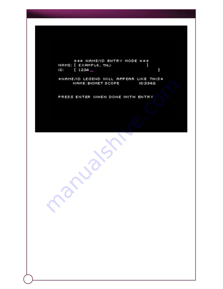
Note: All of these fields are upper case only.

The cursor initially sits in the Name field. Use your keyboard to enter a Name
(or edit the current Name). The name field allows a maximum of 15 characters

Press the Tab key to move to the ID field and enter (or edit) an ID. 

When you are finished entering this information, press the Enter key on your 
keyboard to accept it and exit this mode.

3.1.5.5 Capturing Images

Three ways to activate a capture on  MediaCaptureUSB: 
  1. Press the Stop/Enter button under the OnPoint

 display.

  2. Press the F9 key on the optional, attached keyboard.
  3. Press the Capture button on your camera. 

3.1.5.5a 

Still Capture Mode

Activate the capture for about one (1) second. The light above the Stop/
Enter button will blink once and the system will beep. The image that
appears on the OnPoint display at the time you press this button is the
image that will be captured. It will be saved on the card as a “JPEG (.JPG)” 
graphics file. The file’s name will be based on the date & time it was 
captured (e.g. “MM-DD-YY-HH-MM-SS.JPG”).

When you have finished with this image capture, the OnPoint


system will

return to Still Capture Mode.

21

Summary of Contents for OnPoint

Page 1: ...OnPoint Operation and Care Manual 1 2mm Scope System Anticipate Innovate TM Manufactured by BioVision Technologies LLC Manufactured for ...

Page 2: ...nical Specifications 2 3 Safety Information 3 0 Setup and Basic Usage 3 1 Setup 3 1 1 OnPoint System 3 1 2 Attaching a Camera System and Endoscope s 3 1 3 Attaching External Video Devices 3 1 4 Attaching Virtual Reality Glasses 3 1 5 Setting Up and Operating MediaCaptureUSB 3 1 5a Still Capture Mode 3 1 5b Video Capture Mode 3 1 5c Reviewing Images 3 1 5 6 Set Up 3 1 5 7 Set Recording Time Limit 3...

Page 3: ...ions in this manual carefully before using the OnPoint 1 2mm Scope System Carefully follow all safety instructions to prevent injury to the user or patient fire hazards electrical shock and damage to the device To maintain this device in optimal condition follow all recommendations in this manual for handling cleaning and storage Table of Contents 3 1 5 15 VGA Gamma Set Up 3 1 5 16 Print File Form...

Page 4: ...e system approach Integrated Video Display with Multiple Outputs The OnPoint high resolution 6 4 LCD monitor combines the performance of the Xenon Fiber Optic Light Source and High Resolution Camera System to deliver a brilliant high resolution video image for clear detail recognition and outstanding color reproduction Multiple Output options on the OnPoint unit allow you to connect larger externa...

Page 5: ...procedures For other contraindications consult the literature accompanying the instrumentation utilized with this device 1 4 Regulatory Compliance The OnPoint 1 2mm Scope System complies with all regulations to be marketed in the United States of America Canada and the European Union This device complies with EN60601 1 and all collateral standards This device complies with part 15 of the FCC rules...

Page 6: ... voltage power supply network that supplies buildings used for domestic purposes Harmonic Emissions IEC 61000 3 2 Class A Voltage Fluctuations Flicker Emissions IEC 61000 3 3 Complies Guidance and Manufacturer s Declaration Electromagnetic Immunity The OnPoint is intended for use in the electromagnetic environment specified below The customer or the user of the OnPoint should assure that it is use...

Page 7: ...omet Microfixation for warranty service The product to be repaired must be returned in its original box and packaging or a similar box and packaging affording an equivalent degree of protection Upon completion of repairs Biomet Microfixation will return the product to the end user freight prepaid The warranty period for replacement parts shall begin upon shipment of same but shall in no event exce...

Page 8: ...bed operation and care of the OnPoint 1 2mm Scope System 1 7 Manual Conventions This manual adheres to a set of conventions to help you easily find the information you need and inform you of important information that will help you efficiently and effectively use your equipment Sections and sub sections are noted as follows Special and important information is called out using notes and warnings N...

Page 9: ...mponents are missing contact Biomet Microfixation immediately using the contact information below Biomet Microfixation 1520 Tradeport Drive Jacksonville FL 32218 2480 Phone 800 874 7711 or 904 741 4400 www biometmicrofixation com Alternating Current Fuse Storage Humidity Transport Temperature European CE Mark PRODUCT SERVICE TUV Nationally Recognized Testing Laboratory NRTL Mark Federal Communicat...

Page 10: ...nnection Mode Delete Left Select Right Select Stop Enter Power Indicator Power Button Speaker Ventilation Exhaust Integrated LCD Monitor CompactFlash Media Slot Camera Connector Light port S Video Ventilation Exhaust VR Connector Composite Video Fuse Holder Power Connector KEYPAD OnPoint Scope System 9 ...

Page 11: ... Handpiece Camera POD Camera Handpiece Camera Connector Scope Coupler Focus Knob Image Capture Button Scope Cannula Sliding Sleeve Scope Probe Cannula Cannula Luer Fitting Coupler Scope Handle Scope Fiber optic cable Alignment Dot ...

Page 12: ...deo output 3 NTSC Composite 75Ω 4 pin VR glasses connector Display type LCD 16 25 cm 6 4 in TFT active matrix 960Hx 234V Light Source Type Xenon Arc Lamp BL35WXe Power 35W MediaCaptureUSB Storage media CompactFlash Still image file format JPEG Still image size 640x480 pixels Video file format AVI MJPEG codec Video size fram rate 640x480 pixels 30fps Compatible Camera Attachments Needlescope 24 300...

Page 13: ...nction during a procedure no further visualization is necessary and the procedure is ended the physician shall remove the arthroscope and proceed with closure or further patient care as needed Further arthroscopic examination shall only be performed with a fully functional system for which a backup unit is recommended To avoid personal injury and damage to this device Do not block ventilation slot...

Page 14: ...oes not operate properly the device does not turn on or the performance of the device is noticeably different The device displays signs of tampering or damage such as damage to the power cord broken enclosures etc WARNING In the event of use with other energized endoscopically used instruments and accessories the PATIENT LEAKAGE currents may be additive WARNING Possible explosion if used in the pr...

Page 15: ...drawn to the fact that local laws take priority over the above mentioned requirements If in doubt consult your local representative or the technical service department Zusätzliche Geräte die an medizinische elektrische Geräte angeschlossen werden müssen nachweisbar ihren entsprechenden IEC oder ISO Normen entsprechen z B IEC 60950 für datenverarbeitende Geräte Weiterhin müssen alle Konfigurationen...

Page 16: ...or will power up within about fifteen 15 seconds Hold the distal tip of the scope approximately 2 0cm from a surface with fine details such as your palm or surgical drape Turn the focus adjustment knob in either direction until the fine detailed surface at the distal end of the scope comes into optimal focus on the LCD video monitor See also 3 2 2 Setup for Each Procedure Connect the scope to the ...

Page 17: ... To make these connections plug the connecting cable s into the video output s on the rear of the OnPoint and the corresponding video input s of the external devices A BNC to RCA adapter is supplied with the OnPoint for use with an RCA cable so that such connections can be made with an RCA cable as well as a BNC cable The adapter allows an RCA cable to be plugged into the BNC video output on the r...

Page 18: ... connected to a standard camcorder Consult your camcorder manual for the corresponding connections S Video Cable not included BNC to RCA Adapter included RCS Cable not included BNC Cable not included VCR DVR Camcorder S Video Cable not included BNC to RCA Adapter included RCS Cable not included BNC Cable not included OnPoint Scope System 17 ...

Page 19: ...ile field via the camera connected to the system Your hand never has to leave the camera to capture what you need Note All functions that appear on the OnPoint display are also projected on any external display e g computer monitor BioVision VR glasses etc 3 1 5 1 Modes The MediaCaptureUSB has three separate modes of operation 1 Still Capture Mode for capturing still images pictures 2 Video Captur...

Page 20: ...o image captures Note The OnPoint system will beep every time you press a button on the MediaCaptureUSB panel just under the OnPoint display To move between the different modes in the above order press the Mode button under the OnPoint display or press the F5 key on your keyboard 3 1 5 2 Accessories Attachments You can also connect different accessories to your OnPoint system Note Refer to Section...

Page 21: ... provides a window on your main computer monitor that mirrors the OnPoint display Note If you have not already installed the MediaCaptureUSB software on the appropriate computer you will need to do so at this point Disable all virus protection software on this computer and close any other programs that may be running Locate the MediaCaptureUSB software start the installation program install exe an...

Page 22: ...ureUSB 1 Press the Stop Enter button under the OnPoint display 2 Press the F9 key on the optional attached keyboard 3 Press the Capture button on your camera 3 1 5 5a Still Capture Mode Activate the capture for about one 1 second The light above the Stop Enter button will blink once and the system will beep The image that appears on the OnPoint display at the time you press this button is the imag...

Page 23: ... on the card as a Wave WAV audio file The file s name will be based on the date time the image was captured e g MM DD YY HH MM SS WAV please note that both the still image file JPG and the audio tag file WAV will have the same name When you have finished with this image capture the OnPoint system will return to Still Capture Mode If you want to immediately review this image capture press the Mode ...

Page 24: ...eturn to Video Capture Mode If you want to immediately review this image capture press the Mode button F5 key twice to switch to Review Mode The image you just captured should appear highlighted in the upper left corner of the thumbnail gallery with a VIDEO label Press the Stop Enter button F9 key to review the entire video file 3 1 5 5c Reviewing Images To switch from capturing images to reviewin...

Page 25: ...the F7 or F8 keys respectively To return to the thumbnail gallery displaying four 4 images at a time press the Stop Enter button F9 key again To delete the currently highlighted image press the Delete button or the F6 key The following menu will appear Remove Current Record deletes the currently displayed image from the card Remove All Records on Card deletes all images from the card Press the Sel...

Page 26: ...de when you selected the Setup Mode then you will be returned to the Still Capture Mode etc The following section describes each Setup option in greater detail 3 1 5 7 Set Recording Time Limit This option pertains to Video Mode only Press the Select or Select buttons or the F7 or F8 keys respectively to highlight one of the following recording time limit options for video captures and then press t...

Page 27: ...lect F7 button to move to the Day of the Date and make the same adjustments Then do the same with the Year Hour and Minutes adjusting the Minutes will reset the Seconds to 00 When you are finished adjusting the Date and Time press the Done Stop Enter F9 button to set them and return to the Setup menu 3 1 5 9 Set Audio Setting This option allows you to add an audio tag to every image or video you c...

Page 28: ...ess is complete you will return to the File System Manager screen To cancel this process press the Stop Enter button F9 key You will return to the File System Manager screen 3 1 5 12 OSD Overlay Position This option allows you to adjust the vertical positions of the Name ID and Date Time strings that are included with every image you capture Note The Name ID string appears at the top of the displa...

Page 29: ...both still and video images to be stored using a single button on the camera When in Dual Mode Button pressing the camera button will store still image If the button is held down for two 2 seconds the system will start storing video Pressing the button again will stop video recording Single Mode Button This moder allows for audio to be recorded with still images if Audio Tag recording is enabled T...

Page 30: ...he bottom of the unit is in the correct position for the line voltage in your area The switch has two positions 115V and 230V 115V is for U S use 230V is typically for use in Europe System Power Switch Turn on the OnPoint unit by pressing the Power button just below the Integrated Video Display The lamp will start operating immediately Approximately fifteen 15 seconds later MediaCaptureUSB will di...

Page 31: ...ing fuses etc 3 2 3 Single use Endoscope Disposal When disposing of the single use endoscope and endoscope accessories follow procedures for biologically hazardous materials 4 0 Cleaning and Maintenance The following section describes the proper method s for cleaning and maintaining your OnPoint system Note Never immerse or soak any part of the OnPoint system in any liquid as this can cause signif...

Page 32: ...25 LAMP HOURS REMAINING 20 seconds 1 5 REPLACE LAMP 30 seconds 0 REPLACE LAMP 120 seconds 1 877 304 3738 Field replacement of the lamp should never be attempted For service contact your Biomet Microfixation representative 31 4 4 Recommendations for the Disposal of the Device For the disposal of the OnPoint unit follow the guidelines in Directive 2002 96 EC Waste Electrical and Electronic Equipment...

Page 33: ...Operation and Care Manual WARNING USE 3 15A 250V TYPE F FUSES ONLY 4 Place the fuse holder back in the unit Push firmly until it snaps into place 32 3 Disengage the fuses as shown Replace with new fuses ...

Page 34: ...per building administration to ensure power to your outlet 5 Should these measures fail please contact Biomet Microfixation for technical support and or service B The unit s fans are blowing but the monitor is blank 1 Ensure the camera cable connector is properly seated in the receptacle on the front of the unit See 3 2 2 Setup for Each Procedure 2 Check for light output If there is none replace t...

Page 35: ... the output is still low or there is no light your lamp may be bad Please contact your service representative See 4 3 Lamp Replacement 3 If your lamp is good or is now replaced and light output is now still low the light fibers in the camera cable may be damaged Please contact Biomet Microfixation for service Please copy your serial number here for future reference 34 Biomet Microfixation 1520 Tra...

Page 36: ...tmicrofixation com EUROPE Toermalijnring 600 3316 LC Dordrecht The Netherlands Tel 31 78 629 29 10 Fax 31 78 629 29 12 e mail europe biomet com Authorized Representative in EC Biomet U K Ltd Waterton Industrial Estate Bridgend South Wales CF31 3XA U K Phone 44 1656 655221 Fax 44 1656 645454 r11k1101 OnPoint Scope System is manufactured by BioVision Technologies LLC Manufactured for BVT93571 00003 ...

Reviews: