22
Chapter 3. Hardware assembly
STEP 5.
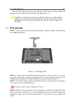
Connect the X1 sockets’ power connectors to the motherboard using the custom
Y-shaped power cable included in the package. The power connector that is used for this
purpose is located on the motherboard right next to the main power connector.
STEP 6.
Depending on the number of cards that will be inserted into the device, remove
either blanking plate 1, or both blanking plates from the back plate of the case.
3.6
Inserting cards
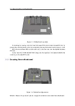
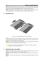
Figure 3.7: Inserting analog card to the T-frame side.
STEP 1.
Insert the cards into their respective X1 sockets. The figure 3.7 shows only the
card attached to the T-frame side, while the procedure for other card is the same, it is just
placed in the socket attached to the left side panel.
STEP 2.
Attach the cards with the screws wherever you see the holes on the cards align
with the holes on the aluminium lips of the bottom plate.
N
If using analog cards, prepare their modules in a way that they do not skip any module
insert places to avoid any recognition issues.
3.7
Attaching other case plates
STEP 1.
Attach the back plate to the case, but be careful to match all the cutouts on it with
the connectors and LED on the card(s) and the motherboard.
STEP 2.
Attach the front plate as well and make sure cutouts for LEDs and reset button are
aligned.
STEP 3.
Cover the case with the top cover and attach it using the previously removed four
screws.

