- 17 -
USE
INSTRUCTIONS FOR USE
tem.
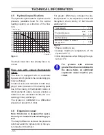
The control of the set temperature reached
can be seen on the LCD display by means
of the missing symbol
.
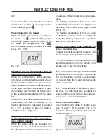
Power request in c.h. power.
When the boiler has a power request in the
c.h. mode, the
symbol is displayed on
the display followed by an increase of the
c.h. water flow temperature. The
symbol flashes and the circulator is activat-
ed
(Fig. 2.10).
Fig. 2.10
Adjusting the c.h. temperature with the
external temp. probe installed
When the external temp. probe (optional)
is installed your boiler automatically adjusts
the temperature of the c.h. system water
flow in relation to the external temperature.
In this case the boiler must be set by a qual-
ified installer (see "Setting the K coefficient
of the external temperature probe" to page
60).
However, if the ambient temperature is not
comfortable, the flow temperature of the
heating plant can be increased or reduced
by ± 15°C by acting on keys 15 (reduce)
and 16 (increase) (Fig. 2.7).
Regulation of heat temperature, inde-
pendent, between the two areas with re-
mote control installed
When the zone valves are installed one
controlled by the ambient thermostat and
the other by the remote control it is possible
to have two different heat delivery tempera-
tures.
The heating temperature of the zone valve
controlled by a thermostat is configured on
the boiler control panel using keys 15 and
16 Fig. 2.7.
The heating temperature of the zone valve
controlled by remote control is configured
using the heating temperature regulation
keys on the remote control.
Setting the heating time brackets for
zone 1 (room/TA zone)
In order to satisfy a heating request, both
the TA and the clock must be activated.
The second zone on the other hand is man-
aged independently from the remote (so it
already has its own time brackets).
N.B.: In the case of a single zone controlled
by TA and boiler clock (where programmed
with time brackets), in order to have a heat-
ing request, both the TA and clock consents
must be obtained.
N.B.: The scheduling of the heating brack-
ets does not affect possible requests for
system antifreeze (AF) which are satisfied,
irrespective of the time bracket set.
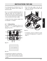
To set the time brackets:
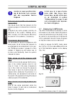
Enter ”programming mode” by holding down
keys 16 and 17 for 5 seconds (Fig. 2.12)
until the LCD display indicates the symbols
shown in Fig. 2.11.
Fig. 2.11
Summary of Contents for Activ A 25S
Page 79: ... 79 MAINTENANCE MAINTENANCE Fig 9 25 Winter ...
Page 82: ... 82 NOTES ...
Page 83: ......


