Beta LaserMike LASERSPEED 8000 Instruction Handbook Manual Download Page 68


LaserSpeed 8000/9000 I/O Module Instruction Handbook 

Operation 


Part No. 93342 / Drawing No. 0921-01516 

Page 68 of 84 

                     Revision E (Dec 2013) 
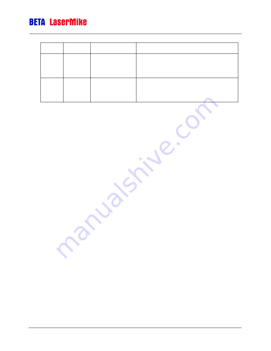
78 

4.7 

Reserved 

8-bit byte - Don't use (set to 0) 

79 

4.8 

User Update Rate 

8-bit byte 

User Update Rate Setting 

Serial Command: "O" 

80 (start) 
↓ 

95 (end) 

5.0 (start) 
↓ 

5.15 (end) 

Gauge Version 

String (8 bit, NULL terminated  char array)     
Gauge Firmware String (similar to "LS9KVC" 

Serial Command: "Z" 


Summary of Contents for LASERSPEED 8000

Page 1: ...SPEED 8000 9000 I O MODULE INSTRUCTION HANDBOOK installation setup technical reference Manual Part Number 93342 Manual Drawing Number 0921 01516 English Revision E Copyright Dec 2013 www betalasermike...

Page 2: ...ts 16 Parallel Outputs 20 Elongation Synchronization 24 Master Slave I O Modules 24 Synchronization 26 Elongation Differential Speed Calculation 27 Setup 28 Data Format 28 Serial Communications 31 I O...

Page 3: ...e place of its use and under conditions of its use EXCLUSIONS This warranty does not cover products which have been modified altered or repaired by any other party than Beta LaserMike or its authorize...

Page 4: ...the relevant items of equipment are properly and securely earthed to a common earth point using adequately sized cable or other means of connection Where supplied or specified shielded interconnectio...

Page 5: ...LaserSpeed 8000 9000 I O Module Instruction Handbook Declaration of Conformity Part No 93342 Drawing No 0921 01516 Page 5 of 84 Revision E Dec 2013 Declaration of Conformity...

Page 6: ...s equipment must be earthed grounded Relays and associated wiring are rated for SELV levels i e 60 Vdc 30 vac rms These levels must not be exceeded Maintenance repairs and electrical connections shoul...

Page 7: ...O Module connects to the LS9000 LS8000 gauge through a gauge cable via an RS422 connection and provides a pass through connector for direct access to all the Inputs and Outputs of the LS9000 LS8000 Se...

Page 8: ...n about connections to the Gauge Power Accepts IEC 320 power cords AC power requirements are 90 260VAC 50 60Hz 1 5Amps I O Setup A computer can be connected to this port using a straight through 9 pin...

Page 9: ...asses signals from the DB25 connector on a LS9000 LS8000 The pinout of this connector is compatible with 25 pin LaserSpeed breakout boxes Signal descriptions are listed in a table below ETHERNET Pass...

Page 10: ...ule s position in the system All I O Modules except for the last I O module in the Daisy Chain calculate the Elongation Ratio or Differential Speed The last I O module in the Daisy Chain always output...

Page 11: ...nnections pre wired Beta LaserMike recommends that you use the supplied key switch to operate the Laser Interlock This will provide you with a laser shutoff for maintenance or material changes Pin 18...

Page 12: ...Input 15 Phase A True User Selectable 16 No Connection 17 No Connection 18 Length Reset 1 19 Signal Ground for Inputs Outputs Serial 20 User Vin Voltage Input for Isolated Pulse Outputs 5 to 28 V DC T...

Page 13: ...asurement Direction Input 1 15 Phase A True User Selectable 16 Laser Interlock 17 Shutter control 18 Length Reset 1 can be activated by I O Module 19 Signal Ground for Inputs Outputs Serial 20 User Vi...

Page 14: ...c input 34 Ethernet tx 35 Ethernet rx 36 Ethernet tx 27 Ethernet rx Note 1 User Input requiring 5 to 28 V to activate General Note The Laser Interlock is in series with the front panel switch Gauge RS...

Page 15: ...nnect 9 NC Notes Pin 1 or Red on the Light Stack is active when the Status Input from the LS9000 LS8000 shows power is being sent to the laser and that the Shutter is open Pin 2 or Yellow on the Light...

Page 16: ...at is Calculated in the I O Module Speed Outputs the Velocity measurement from the gauge Status Signals Status Signals pins numbered 1 16 are generated as solid state closures The contacts close when...

Page 17: ...Closure Output indicating if the Laser Power is on Closed Laser is ON Open Laser is OFF 8 Laser Power Output 9 Reserved Output Reserved Contact Closure Output Do Not Connect 10 Reserved Output 11 Lase...

Page 18: ...configurable An output of 0V corresponds to the Minimum Elongation and an output of 2 048V corresponds to the Maximum Elongation 33 GND Elongation Analog Output ground 34 Velocity Analog Output Veloci...

Page 19: ...are used for various analog outputs Every I O Module contains three analog outputs Elongation Analog Output only used when using multiple I O modules are configured for Synchronization Velocity Analog...

Page 20: ...rovided to indicate when data has been upated and is valid The Data Ready pulse indicates that the data bus has been updated with new data and that the signals on the bus are completely settled Both D...

Page 21: ...ed with a serial command See the RS 232 Configuration Commands section for details Choosing the correct polarity of Data Ready is important Improper polarity choice can lead to data that appears to be...

Page 22: ...Data Ready Response Time T3 570 s nominal Data Hold Time T4 120 s min Data Setup Time T5 300 s min Data Ready Pulse Width T6 ReadyLn x 500 s Note T6 is set using the serial command I ReadyLn X where X...

Page 23: ...age 23 of 84 Revision E Dec 2013 Example If data is required every 2 ms the PLC should pulse the Data Request signal every 2ms The Data Ready Pulse Width should be configured to be less than half the...

Page 24: ...atio If 1 ms user update rate is selected in the gauge the I O Module will only update its outputs every 2 ms Master Slave I O Modules I O Modules can either be masters or slaves depending on where th...

Page 25: ...ongation feature is enabled for the Parallel Data Output This feature automatically switches the Length Elongation port to output Elongation Ratio Differential Speed when available The last gauge in t...

Page 26: ...m Each Slave in the system will replicate the Synchronization signal sending the Synchronization signal to its gauge and outputting it on its Synchronization out connector All Slaves can be Daisy chai...

Page 27: ...the I O Module connected to the SYNC IN connector The connected I O Module receives this velocity and calculates elongation using the following formula where V1 is the velocity of the slave gauge V0 i...

Page 28: ...it Meters Min 0 001 meters bit 0 001 m 1 mm sec bit The largest length that can be measured is 999 999 999 meters mm feet yards or inches To output the decimal number as an integer it is multiplied by...

Page 29: ...a bit 1 20 20 Data bit 20 219 2 Data bit 2 21 21 Data bit 21 220 3 Data bit 3 22 22 Data bit 22 221 4 Data bit 4 23 23 Data bit 23 222 5 Data bit 5 24 24 Data bit 24 223 6 Data bit 6 25 25 Data bit 25...

Page 30: ...7 Data bit 7 26 26 Sign 8 Data bit 8 27 27 Quality LSB 20 9 Data bit 9 28 28 Quality LSB 21 10 Data bit 10 29 29 Quality MSB 22 11 Data bit 11 210 30 Quality MSB 23 12 Data bit 12 211 31 Data Ready 1...

Page 31: ...I O module The second link is a RS 422 serial connection between the I O Module and the LaserSpeed gauge Each link has its own Baud Rate and Framing Parameters Both the RS 232 connection between the...

Page 32: ...O module off wait 60 seconds then power back on On power up the I O module will output the following message at 115200 Baud Rate 8 data bits 1 stop bit No Parity Waiting 2sec to start A to abort Confi...

Page 33: ...by the I O Module the I O Module will respond with a validation error and the entire command will be ignored B Gauge_Serial BaudRate 115200 StopBits 2 DataBits 7 Parity NONE SyncMode 0 ElongAvg 10 B9...

Page 34: ...e Type Y Master Slave Connection Status Z I O Module Software Revision A MaxVel Analog Output Maximum Velocity A MaxVel CR Read Setting Response Format Analog MaxVel N CR A MaxVel N CR Set Value Facto...

Page 35: ...nalog output of 0 0 Volts to 100 m min When the measured velocity is 100 m min the analog output will be limited to the minimum output voltage of 0V A MaxElg Analog Output Maximum Elongation A MaxElg...

Page 36: ...m value of 0V This value can be a positive or negative value or can be zero Example Sending the command A MinElg 0 CR will set the minimum elongation ratio analog output to 0 0V when the elongation ra...

Page 37: ...ity 300 Min Velocity 100 Max elongation ratio 5 Min elongation ratio 0 To calculate the velocity from the analog voltage use the following formula Velocity To calculate the elongation ratio from the a...

Page 38: ...ata Bits 7 8 P Parity Should always be set to NONE M Sync Mode 0 or 1 E Elongation Averaging Number of elongation readings to average from 1 to 1000 Default 10 This command configures the baud rate an...

Page 39: ...ng should be set to 1 and all gauges H settings set to 9 This will allow the I O Module to rely on the gauge s synchronization output timing for increased performance This is required when operating s...

Page 40: ...e Command 230400 8n1 11 CR B230400 1 8 None CR 7n2 1 CR B230400 2 7 None CR 115200 8n1 12 CR B115200 1 8 None CR 7n2 2 CR B115200 2 7 None CR 57600 8n1 13 CR B57600 1 8 None CR 7n2 3 CR B57600 2 7 Non...

Page 41: ...be set to 0 A should be set to 0 for normal operation Mode A Description 0 Normal Operation 1 Cycle Front Panel Lights 2 Simulate Normal Operation F IP Ethernet IP Address F IP CR Read Setting Respons...

Page 42: ...ed when the I O Module is equipped with an Ethernet fieldbus card Example To set the NetMask to 255 255 255 0 send the command F Netmask 255 255 255 0 CR F Gateway Ethernet Gateway Address F Gateway C...

Page 43: ...is setting is only used when the I O Module is equipped with an Ethernet fieldbus card Example To set the UDP Port 4750 send the command F UdpPort 4750 CR F TcpPort Ethernet TCP Port F TcpPort N Read...

Page 44: ...ss to which UDP data messages will be sent This setting is only used when the I O Module is equipped with an Ethernet fieldbus card Example To set the UDP Destionation Address to 192 168 10 111 send t...

Page 45: ...thernet TCP Port UI Ethernet UDP Destination Address This setting is only used when the I O Module is equipped with an Ethernet fieldbus card Example To set the UDP Destination Address to 192 168 10 1...

Page 46: ...lPort StrobeFlag N CR I StrobeFlag N CR Set Value Factory Default 1 Minimum 0 Maximum 1 Where N indicates the polarity of the Data Request input signal When the I O Module s parallel port is in Data R...

Page 47: ...Factory Default 1 Minimum 0 Maximum 1 Where N indicates the polarity of the output Data Data true high or Data true low Value Logic 0 Logic 1 0 High Voltage Low Voltage 1 Low Voltage High Voltage When...

Page 48: ...eady Mode 1 Data Request Mode When in Data Ready Mode the I O Module automatically updates the parallel port when new data is received from the gauge The update rate is determined by the gauge s updat...

Page 49: ...integer value from 1 to 255 This allows a pulse length from 500 s to approximately 125ms in 500 s increments The value for this setting can be calculated with the following formula Example To set the...

Page 50: ...tput length Example To enable Auto Elongation Mode send the command I Elongation 1 CR To disable Auto Elongation Mode send the command I Elongation 0 CR I ElongRes Parallel Port Elongation Resolution...

Page 51: ...t ElongRes N CR I LenRes N CR Set Value Factory Default 1 Minimum 0 001 Maximum 1 Where N indicates the Length resolution multiplier Value Length Multiplier 1 Length x 1 0 1 Length x 0 1 0 01 Length x...

Page 52: ...on multiplier Value Velocity Multiplier 1 Velocity x 1 0 1 Velocity x 0 1 0 01 Velocity x 0 01 0 001 Velocity x 0 001 This command allows to user to reduce the output resolution of the velocity measur...

Page 53: ...ty Factor Status This setting must match the display type defined by AM used with the system I I Parallel Port Configuration Settings I CR Read All Settings with labels Example Response Format Paralle...

Page 54: ...tive High default A Parallel Port Update Mode 0 Data Ready Mode default 1 Data Request Mode L Parallel Port Data Ready Strobe Length 0 255 E Parallel Port Elongation Mode 0 Disabled 1 Enabled default...

Page 55: ...sponse Format 115200 1 8 None CR Where B S D and P are as follows Parameter Description Valid Values B Baud Rate 230400 115200 57600 38400 19200 4800 S Stop Bits 1 2 D Data Bits 7 8 P Parity Odd Odd P...

Page 56: ...data bits and no parity send the command J115200 2 7 None CR O O Profibus Ethernet Byte Order Endianness O CR Read Setting with labels Example Response Format BigLittleEndian Order 1 O N CR Set Value...

Page 57: ...se Format Master X1 Slave X2 Where M indicates if a Master is connected and S indicates if a Slave is connected This command returns the connection state of the rear panel Sync In and Sync Out connect...

Page 58: ...owing listing in response to the H CR command B Gauge_Serial BaudRate 115200 StopBits 2 DataBits 7 Parity NONE SyncMode 0 ElongAvg 10 Status Port 2 BaudRate 115200 StopBits 2 DataBits 7 Parity N Norma...

Page 59: ...enRes 1 VelRes 1 DisplayType 0 Status ReadyOut INVERT DataReqIn INVERT DataOut INVERT AckMode DATA RDY MODE ReadyLength 14 0ms Len ElongOutput LENGTH ElongRes 1 000 VelRes 1 000 LenRes 1 000 DisplayTy...

Page 60: ...will not work Check the lights on the front panel of the I O Module to see it they are functioning properly The I O Module to Gauge communication link is not working when the front panel lights are n...

Page 61: ...on the rear panel on the connector labeled STATUS The Key Switch must be on and the Interlock must be active to turn on the Laser Interlock Indicator This indicator is lit when power is supplied to t...

Page 62: ...cted Status indications are described in the LaserSpeed I O Module Operator Guide Profibus Command Structure Values are updated every time the LS9000 LS8000 is updated The Status Command Velocity Leng...

Page 63: ...r writes appropriate data into the Output Data Block and then sets the LS nibble of its PUV Command Status to 0x01 hexadecimal value to begin the initialization process The I O Module reads the PUV va...

Page 64: ...ds and begins a configuration sequence when the PUV 0x02 The I O Module gets the configuration parameters from the gauge and updates Master s Output Data block then writes 0x02 back to the Master s PU...

Page 65: ...s Gauge Version Byte 2 Block Byte Word Description Format 0 0 0 PUV Register 8 bit byte See below for PUV Register Format 1 2 3 4 1 0 1 1 1 2 1 3 Velocity 32 bit 2 s complement signed integer represen...

Page 66: ...n Time 32 bit unsigned integer Material Present Validation Time Setting Serial Command G 35 msb 36 37 38 lsb 2 10 2 11 Hour Meter 32 bit unsigned integer Read Only Hour Meter Indicates Hours of Operat...

Page 67: ...67 msb 68 69 70 lsb 3 10 3 11 Material Present Threshold 32 bit unsigned integer Material Present Threshold Setting Serial Command M 71 4 0 Reserved 8 bit byte Don t use set to 0 72 4 1 Baud Rate 8 bi...

Page 68: ...ge 68 of 84 Revision E Dec 2013 78 4 7 Reserved 8 bit byte Don t use set to 0 79 4 8 User Update Rate 8 bit byte User Update Rate Setting Serial Command O 80 start 95 end 5 0 start 5 15 end Gauge Vers...

Page 69: ...ation settings transmitted in the Profibus Data Exchange message to the attached LaserSpeed gauge READ_STATUS The I O Module sets this bit in its output Profibus message in response to the Profibus ma...

Page 70: ...Event Note MEASUREMENT DATA IS NOT VALID BETWEEN EVENTS A AND C Event A Profibus Master Sets READ_SETUP bit PUV bit 1 to 1 I O Module reads this bit and begins reading setup from the LaserSpeed gauge...

Page 71: ...ENT DATA IS NOT VALID BETWEEN EVENTS A AND C Event A Profibus Master Sets WRITE_SETUP bit PUV bit 0 to 1 I O Module reads this bit and begins writing setup to the LaserSpeed gauge It then verifies the...

Page 72: ...a MP Material Present Status Bit 0 Material is Not Present 1 Material is Present VALID Valid Measurement Status Bit 0 LaserSpeed gauge is not making measurements 1 LaserSpeed gauge is making valid mea...

Page 73: ...eldbus side Flashing Red 1 Hz Error in configuration IN and or OUT length set during initialisation of the module is not equal to the length set during configuration of the network Flashing Red 2 Hz E...

Page 74: ...fibus DB9 Connector Pinout Pin Pin Name Description 1 Not Connected 2 Not Connected 3 B Line Positive RxD TxD according to RS 485 specification 4 RTS Request to Send 5 GND BUS Isolated GND from RS 485...

Page 75: ...P Port Port number for UDP broadcast This is the port the Master should use to receive data Default 4750 TCP port TCP port for sending and receiving setup data Default 4751 Gateway 0 0 0 0 Mask 255 25...

Page 76: ...ange 5 The I O Module checks for any differences in the Ethernet to what s in the LS9000 LS8000 6 Any changed values are updated to the LS9000 LS8000 7 Bit 1 is cleared in the Status Command byte when...

Page 77: ...art r o 4 PulseUnitHigh L pulse per unit length 4 AnaZero N analog zero value 4 PulsePerUnitLow P Pulse per unit length low speed 4 Calibration TC reads calibration number 4 WalkThresh W walking thres...

Page 78: ...not be able to initialize Please contact your supplier Red 2 Hz The module failed to load Ethernet configuration from the FLASH Red 4 Hz Internal error Please contact your supplier 3 Modbus TCP connec...

Page 79: ...son to discuss the instrument failure Returning Equipment for Service When returning equipment for service it is important to first obtain a Return Material Authorization RMA number The RMA number is...

Page 80: ...LaserSpeed 8000 9000 I O Module Instruction Handbook Specifications Part No 93342 Drawing No 0921 01516 Page 80 of 84 Revision E Dec 2013 Specifications Stand alone Dimensions Rack Mounting Dimensions...

Page 81: ...LaserSpeed 8000 9000 I O Module Instruction Handbook Specifications Part No 93342 Drawing No 0921 01516 Page 81 of 84 Revision E Dec 2013 Bottom Mounting Dimensions...

Page 82: ...ers 24volts at 0 2 Amp Analog Outputs Voltage output range 0 to 2 048 V RL 10 k Output load regulation accuracy VO 2 048 V RL 2 k 0 25 voltage of FS Ethernet Connection RJ45 not to exceed 30 meters Pr...

Page 83: ...ardware prepared for DP V1 extensions Save Load configuration in Flash supported Enclosure IP50 Environmental Conditions Indoor use Altitude up to 2000m Temperature 5 C to 40 C Maximum relative humidi...

Page 84: ...Material Present 18 Female 37 Pin D Subminiature 13 Front Panel 7 Gauge RS 232 Connector 14 I O Setup Connector 14 Industrial Environment 4 Intended Use 6 Introduction 7 LaserSpeed Communication 60 La...

Reviews: