


LaserSpeed 8000/9000 I/O Module Instruction Handbook
Installation
Part No. 93342 / Drawing No. 0921-01516
Page 22 of 84
Revision E (Dec 2013)
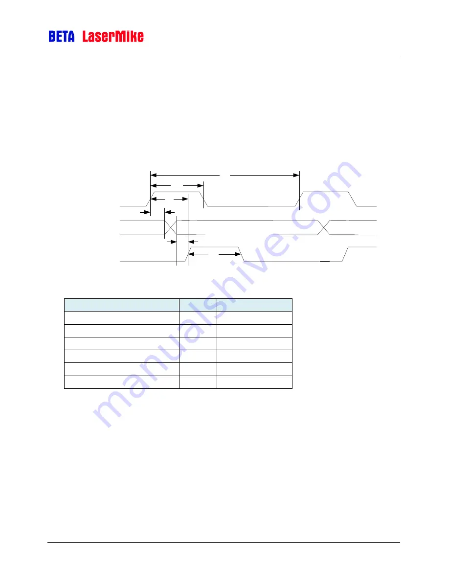
Data Request Mode
When the system is configured for Data Request mode, a "Data Request" signal
issued by the PLC/Control System is used to notify the I/O Module that new data
is requested by your interface. The following figure shows Data Request Mode,
indicating typical waveforms and listing the timing information necessary to use
this mode. "Data Request" is an optically isolated input and requires a pulse
supplied by your interface (5 to 24 volts DC).
Data Request Parallel Port Timing
*Data Ready False has the opposite polarity
Parameter
Symbol
Value
Data Request Period
T1
1 ms (min.)
Data Request Pulse Width
T2
20µs (min.)
Data Ready Response Time
T3
570 µs (nominal)
Data Hold Time
T4
120 µs (min.)
Data Setup Time
T5
300 µs (min.)
Data Ready Pulse Width
T6
ReadyLn x 500µs
Note
: T6 is set using the serial
command “~I:ReadyLn=X”, where X is an integer.
Divide the desired pulse width by 500µs, and use this value for X. When
configured in the "Data Request" mode, any Data Request from either Length or
Velocity will cause all "Data Request" type system outputs to be updated. Data
will remain on the output until a new "Data Request" is received. Only a single
Data Request Line from either the Length/Elongation Connector or the Velocity
connector should be utilized.
Note
: If the Data Ready pulse length is configured to be longer than the Data
Request Period (T6>T1), the Data Ready output will always be high, and erratic
data may be read from the interface. Make sure that you configure the Data
Ready Pulse Width to be half the Data Request Period or less.
DATA_READY*
DATA
T5
T6
DATA_REQUEST
T4
T3
T1
T2