47
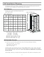
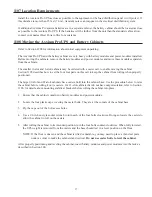
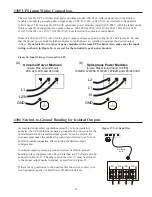
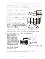
7. If your UPS has an isolated output, find the proper output neutral-to-ground connection in Figure 22. At the
UPS terminals, connect the neutral-to-ground (neutral-to-earth) wire to the proper terminal before
making any other connections to the UPS. The neutral-to-ground wire is a green and yellow wire. One
end of this wire is already connected to the ground (earth) UPS terminal. Ground terminations, inside the
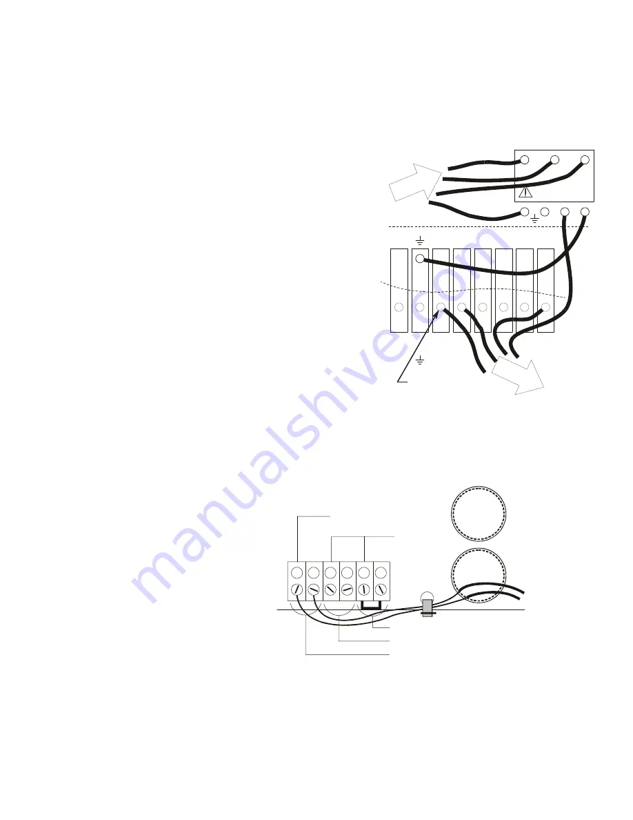
UPS back panel, are located directly below the line input terminals, as shown in Figure 20. Figure 20 shows
input and output wiring terminals inside the Axxium Pro UPS cabinet.
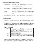
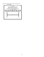
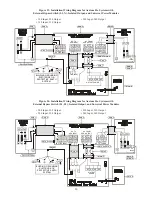
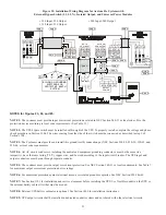
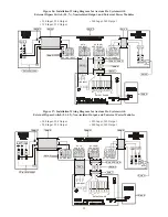
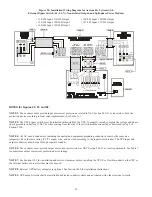
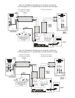
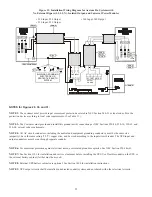
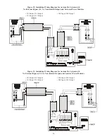
8. Refer to Figures 23 through 34, which show output
configurations for various voltages and isolation options.
Make UPS output connections on the backplane board
terminating studs. Compression lugs (supplied in the
accessory kit) may be installed on the proper terminating
studs. Wires may also be terminated with ring terminals,
which are attached to the output terminating studs.
9. If the bypass switch is an MBB style, notice the cable routed
out of the left side of the bypass switch cabinet. The wires in
this cable must be connected to terminals 3 and 4 in Steps 10
and 11 below.
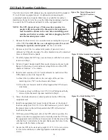
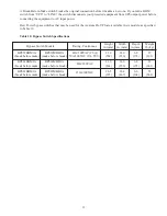
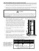
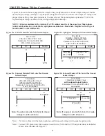
10. If any external, hardwired control signals are required,
remove the rear panel on the upper bay and locate the
terminal block, as shown in Figure 21. CAUTION: EPO and
external bypass circuits are not isolated from line voltage,
and wiring must be installed per local codes using conduit
or suitable primary supply cables.
The Generator On signal is isolated from line voltage and can be treated as NEC Class 2 wiring.
Use 14–20 AWG, 600-V wire (UL) or 14–26 AWG, 300-V wire (CSA) for all input control signals.
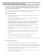
11. Place the signal wires through the
proper conduit or grommet above the
terminal block and attach to
appropriate terminals. Secure each
connection by torquing terminal
screws to a maximum 3.5 in-lb
(0.4 N-m). Provide strain relief for
cables by installing plastic cable ties
as shown in the drawing. NOTE: Do
not strain relieve EPO or external
bypass wiring with the same cable
tie used for On Generator wires.
12. Remove the jumper between terminals
5 and 6 only if you are connecting a
normally-closed EPO switch.
13. When all connections have been made and checked, replace the bypass switch front panel and UPS cabinet
back panels. After installing power and battery modules, install all front cover bezels.
X2
X1
3
X1
+DC
+DC
X2
N
-DC
N
-DC
INP
UT
PO
WE
R
OU
TPU
T
POW
ER
2
1
INPUT CONNECTIONS
(SEE INSTALLATION MANUAL)
Figure 20. UPS Input and Output Terminals
Figure 21. Input Control Signal Wiring
1
2
3
4
5
6
Emergency Power Off (normally closed)
External Bypass
Generator Set
(short to common
when active)
*
Signal
Common
Generator On (N.O.)
*
Backplane board
terminating studs

