background image

26


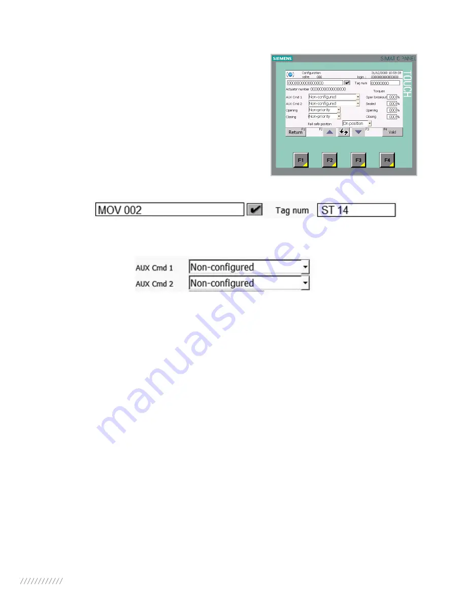
9.2 > CONFIGURE YOUR ACTUATOR

All users’ accounts, except Administrator account, allow 

you to access to this page. But, only the Maintenance 

account will be able to change the actuator configuration.

On this page you can change the Valve reference and the Tag number on these following fields:

You can allocate the auxiliaries commands to the following functions by selecting a parameter in the 

down-drop list of the AUX Cmd 1 and AUX Cmd 2 fields:

•  LOCAL/REMOTE: 

Replace the local/remote selector on the actuator and, under remote control 

conditions, authorize either local control or remote control.

•  LOCAL+REMOTE/REMOTE: 

This function has the same role as the previous one, but local and 

remote control can be authorized simultaneously.

•  PROHIBITING LOCAL CONTROL:

 Prohibiting local control is controlled remotely. This function 

prohibits local opening and closing controls and authorizes remote control even if the actuator 

selector is placed on local control.

•  PROHIBITING OPENING/CLOSING:

 This control is used for preventing the actuator from star-

ting or stopping

•  AUTO / ON-OFF: 

For an actuator used in modulating mode with a positioning function, a com-

mand can be selected by position set-point (equivalent to the 4/20mA signal) or by opening, closing 

or stop controls. The auto/on-off control is used for changing from one control mode to another.

•  CLOSING  /  OPENING  /  EMERGENCY  SHUTDOWN

: The ESD (Emergency Shut Down) is an 

emergency remote command that has priority over the other commands. Depending on the type 

of operation for which the valve is to be used, this emergency command can be opening, closing 

or stopping in an intermediate position. The ESD command is assigned to a Modbus command for 

auxiliary command 1 and to a wired link (separate cabling) for auxiliary command 2.

Note:

 The cabled ESD has priority over the Modbus ESD. Emergency control is not possible when 

the switch is in the OFF position.

Summary of Contents for MS102

Page 1: ...INSTRUCTIONS FOR START UP NR 1182_rev A MASTER STATION MS102...

Page 2: ...2 Setting up using the touch screen Page 20 6 3 Setting up using the MGate manager Page 20 7 SETTING UP THE ETHERNET COUPLER Page 22 7 1 Default parameters Page 22 7 2 Setting up using the touch scree...

Page 3: ...isconnected The Master Station is able to interface with a monitoring computer optional to control directly valves automation This PC workstation equipped with specific software allows to operate the...

Page 4: ...OUR MASTER STATION 3 1 MECHANICAL FIXING Master Station MS102 is composed of one 19 inch unit It must be installed in a 19 inch cabinet Use M6 screws to fix those 8 by unit All connections are accessi...

Page 5: ...ove data routing To assure the redundancy of the system there are several links inside the Master Station MS102 There is a redundent Modbus RTU links and a redundant Modbus TCP Actuator Primary line D...

Page 6: ...on the other hand M2 unit The PLC M5 unit The console touch 3 2 2 LinkthetouchconsolewiththeEthernetSwitch To link the console touch M5 with the Ethernet Switch M9 take the cable labeled C1 which is...

Page 7: ...the other hand M2 unit The PLC M6 unit The web server 3 2 4 Link the Ethernet coupler with the Ethernet Switch To link the Ethernet coupler M10 with the Ethernet Switch M9 take the cable labeled C8 w...

Page 8: ...th the Ethernet Switch M9 take the cable labeled C2 which is pro vided and connect its two RJ 45 connectors entry on the Web server port on the one hand and in the Ethernet Switch input on the other h...

Page 9: ...the Ethernet Switch input on the other hand M7 unit The Modbus RTU TCP Gateway M9 unit The Ethernet Switch 3 3 OUTPUTS LINKS 3 3 1 Link the Profibus lines The Master Station MS102 is an interface betw...

Page 10: ...to 122 For more information refer to the NR1150 Profibus DP V1 for Intelli To get the primary line of the Profibus connect the 9 pins D type connector to the X2 DP port of the PLC M2 on one hand and...

Page 11: ...n equipped with specific software allows you to operate the actuator and to retrieve data and alarms from the field units To link the PC Workstation and the Master Station MS102 together use an Ethern...

Page 12: ...The Modbus RTU connection works via the 9 ways D type connector of the M7 module inside the Master Station M7 Unit is a Modbus RTU TCP gateway Link the first and the second line of the DCS with M7 Uni...

Page 13: ...TCP 3 5 POWER SUPPLY There is a power input on the Ethernet Switch it is powered on by the Power supply labeled M8 Thus you have to wire as shown below wires provided and prewired For more details re...

Page 14: ...ing up the Modbus RTU TCP gateway 4 1 DEFAULT PARAMETERS Default parameters are shown below For the gateway Transmission speed 19200 bauds Format 8 data bits 1 stop bit no parity Communication protoco...

Page 15: ...ministrator right to install MGate Manager Software Moreover you have to connect the computer to the Master Station with an Ethernet cable not provided Connect one of both cable extremity to the Ether...

Page 16: ...t clicking on Browse 4 When the Select Additional Tasks window appears click Next to continue You may select Create a desktop icon if you would like a shortcut to MGate Manager on your desktop 5 Click...

Page 17: ...electing Launch MGate Manager 8 You may also open MGate Manager through Start Programs MGate Manager MGate Manager as shown below 4 3 2 Setting up using MGate manager 1 Run MGate Manager and click on...

Page 18: ...indows Select the one you want to modify and click on Configuration 4 To change the IP address Netmask or Gateway click on Network 5 To change baudrate parity or stop bit click on Serial Click on OK t...

Page 19: ...uitable you can change it as it is explained in part 4 Setting up the Modbus RTU communication If IP addresses of the Web server are not suitable you can change it as it is shown below 5 1 DEFAULT PAR...

Page 20: ...communication and the Web page The Master Station includes some Web pages that may be remotely accessed via Ethernet They can be used for examining the system for any faults or alarms 6 1 DEFAULT PARA...

Page 21: ...the one you want to modify and click on Configuration To modify the IP address of the gateway 1 select MG Ligne1 and to modify the IP address of the gateway 2 select MG Ligne2 4 Select Slave ID Map an...

Page 22: ...on refer to the NR 1178 PC Workstation for MS102 Technical Manual 7 1 DEFAULT PARAMETERS Default parameters are IP address 192 168 94 187 Mask 255 255 252 0 Gate 0 0 0 0 7 2 SETTING UP USING THE TOUCH...

Page 23: ...that the device restarts successfully The Master Station is now ready to run with the new parameters 7 3 SETTING UP USING THE MONITORING PC You can use the PC workstation to change the IP address of...

Page 24: ...tor make sure it is correctly cabled and connected and its slave address is correctly set up To access to the Activate Screen you must be logged in with a Maintenance account To see how log in refer t...

Page 25: ...rmation about the actuator is displayed Refer to part 10 2 Managing your actuators via the touch screen to know more about this screen The communication with your actuator is now established and you h...

Page 26: ...nd closing controls and authorizes remote control even if the actuator selector is placed on local control PROHIBITING OPENING CLOSING This control is used for preventing the actuator from star ting o...

Page 27: ...rity for closing must be configured Giving priority to a direction of rotation If the actuator receives two simultaneous opening and closing orders and an opening priority has been selected the actuat...

Page 28: ...4 these buttons allows you to validate the changes To change the valve reference and the tag number or set up several torques you have to press the corresponding box and enter the appropriate value No...

Page 29: ...are described in Annex User s account User You can only consult information about the Master Station and the actuators connected to it By default Login User Password 333333 Super user Like with the u...

Page 30: ...1 to come back on the main screen Management of user s account To manage user s account you must be logged in with the Administrator account Then you can add an account and set the four parameters whi...

Page 31: ...creen is displayed Buttons description Return or F1 these buttons allow you to come back to Valve selection screen Active this button allows you to access to the Activation Deactivation screen but onl...

Page 32: ...verload activated The actuator will be available again as soon as the motor has cooled down Phase loss fault Only in 3 phase mode one phase is missing No start up allowed Valve too hard Opening or clo...

Page 33: ...rection of rotation non compliant in closing mode Torque sensor supply The actuator no longer receives any information from the position sensor Communication fault There is a communication fault betwe...

Page 34: ...mmanding the valve until it is fully open or F3 these buttons allow you to stop the actuator during operation or F4 these buttons allow you to close the actuator A short pulse will be sufficient for c...

Page 35: ...refer to part 10 1 Log in access For an actuator used in modulating mode with a positioning function a command can be selected by position set point Buttons description or F1 these buttons allow you...

Page 36: ...ge you can consult the following parameters The Operating class On Off Modulating Class II or Modulating Class III The type of the Motor supply 3 phases or 1 phase or DC The Closing mode Closing on po...

Page 37: ...ain the accumulated figures since the actuator manufacturing in seconds STARTS SINCE LAST RESET Number of starts since the last reset RUNNING TIME SINCE LAST RESET Total running time since the last re...

Page 38: ...button allows you to come back to Home screen and F2 this button allows you to access to the Master Station Configuration screen For more information about the configuration refer to paragraph 4 Sett...

Page 39: ...nd one is Alarms History and the last one is Alarms not acknowledged Alarms in progress On this screen you can find the alarms in progress about the Master Station and the actuators Buttons descriptio...

Page 40: ...t It is not sensitive so press F4 Alarms not acknowledged An alarm not acknowledged is an alarm which happened and disappeared before a user see it and acknowledged it On this screen as on the Alarm h...

Page 41: ...n section 3 3 5 the PC can also be connected to the same Ethernet network as the Master Station In any case the PC needs a Web browser such as Internet Explorer to access the Master Station web pages...

Page 42: ...4 ACTUATORS STATUS From the Home page you can access to the Actuators Status pages Click on one of the three buttons which allow access to a list of actuators On this page you can find the position a...

Page 43: ...n yellow it means that the actuator is not active black Not Available it means that the actuator is in default If you select an actuator you have access to its Valve status page Here you can find some...

Page 44: ...the actuator indicate that there is an actuator fault which prevents the actuator from running for the following reasons Torque limiter tripped Loss of communication with Master Station MS102 Motor th...

Page 45: ...ere is a fault communication Profibus communication status line 2 if the light is green it means that the communication between the actuators and the Profibus coupler is running but if the light is re...

Page 46: ...the actuator It is not possible to activate deactivate a valve or to change the actuator configuration MAINTENANCE Master Station MS102 It is possible to change the language to consult the status of t...

Page 47: ...47 NOTES...

Page 48: ...nardcontrols com Tel 1 281 578 66 66 BRAZIL JCN SAO PAULO jcn jcn com br Tel 55 11 39 02 26 00 ASIA Information on our network www bernardcontrols com or To contact our distributors Back Office BERNAR...

Reviews: