


Berges electronic
•
D–51709 Marienheide-Rodt
•
Tel. 02264/17-0
•
Fax 02264/17126
Operating manual
21.12.98
ACP 3000 — 0.37–15.0
04_GB
20
The inverter will be destroyed if the mains feeder is confused with the motor cable.
The DC link capacitors must be reformed if the inverter you wish to connect has been out
of operation for more than a year. To do this, connect the inverter to voltage for approx. 30
minutes. The inverter should not be loaded by connected motors during forming.
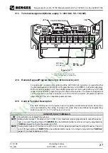
3.6.1
Mains Conditions
Permissible fluctuation of the mains voltage amounts to around ±10% of the rated
voltage. If the mains voltage should exceed or fall below these limits, the inverter will
be deactivated automatically as the result of the undervoltage or overvoltage.
When applying the inverter to line voltages other than the factory default values (230 VAC
or 460 VAC), be sure to set parameter
59-MVOLT
to the proper value. Refer to page 42.
Adaptation to rated line voltages outside the permissible range is possible by means of au-
totransformers. Calculation according to the formula below is recommend:
NOTE:
Exercise caution when using the ACP 3000 under the conditions of a low-voltage network.
An inverter from the ACP 3000 series is fully functional when connected to an alternating
current of 370 V, for example. However, the maximum output voltage is limited to 370 VAC.
If the motor is rated for a mains voltage of 400 VAC, this can lead to higher motor currents
and overheating of the motor. It must be ensured that the connected mains voltage cor-
responds to the rated voltage of the motor.
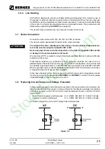
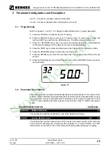
If other than 50 Hz output can be tolerated, proper volts/hertz can be programmed into the
inverter by the
53-FKNEE
and
32-FMAX
parameters. If you are unsure about this feature,
consult section 5.2 or BERGES.
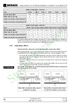
Phase voltage imbalance of the input AC source can cause unbalanced currents and ex-
cessive heat in the input rectifier diodes and in the DC bus capacitors of the ACP. Phase
imbalance is calculated by the following method:
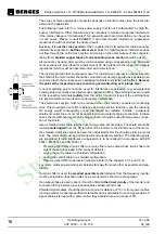
Flow diagram of the requirements relating to the combination of frequency inverter
and residual-current-operated protective device
P
T
= Equivalent two-winding kVA rating (kVA)
P
D
= Continuous output (kVA)
U
1
= Rated line voltage (V)
U
2
= Rated voltage, frequency inverter (V)
I
2
= Input current (A) as per table 2.1 and 2.2
P
T
P
D
1
U
2
U
1
-------
–
=
P
D
U
2
I
2
×
3
×
=
StockCheck.com


