


21.12.98
Operating manual
04_GB
ACP 3000 — 0.37–15.0
13
Berges electronic
•
D–51709 Marienheide-Rodt
•
Tel. 02264/17-0
•
Fax 02264/17126
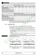
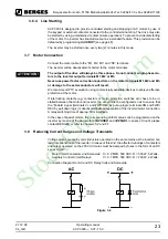
The converter and accessories must be wired in accordance with the following schematic.
To render the remaining interference voltage at the PE conductor potential ineffective for
“external measurement systems”, the following proposed circuit will achieve successful re-
sults if applied consistently.
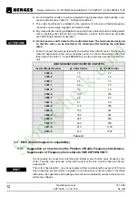
3.3.2
Mains Filters/Output Chokes
ACP 3000
DEVICE TYPE
MAINS FILTER
ARTICLE NO.
INPUT PHASES
VOLTAGE (V)
CURRENT (A)
WEIGHT (kg)
FOOTPRINT
ACP 3300-3
BE I 1005
32501739
1~
250
5
0.60
(1)
(1)
FOOTPRINT means that these filters have been prepared for the installation of an ACP converter on the filter (securing).
ACP 3300-5
BE I 1005
32501739
1~
250
5
0.60
(1)
ACP 3300-7
BE II 1010
32501740
1~
250
10
0.70
(1)
ACP 3301-1
BE II 1010
32501740
1~
250
10
0.70
(1)
ACP 3301-5
BE III 1020
32501741
1~
250
20
1.05
(1)
ACP 3302-2
BE III 1020
32501741
1~
250
20
1.05
(1)
ACP 3600-7
BE I 3003
32501742
3~
380/480
3
0.75
(1)
ACP 3601-5
BE II 3005
32501743
3~
380/480
5
0.80
(1)
ACP 3602-2
BE III 3012
32501744
3~
380/480
12
1.15
(1)
ACP 3603-0
BE III 3012
32501744
3~
380/480
12
1.15
(1)
ACP 3604-0
BE III 3012
32501744
3~
380/480
12
1.15
(1)
ACP 3605-5
BE IV 3038
32501745
3~
380/480
38
1.90
(1)
ACP 3607-5
BE IV 3038
32501745
3~
380/480
38
1.90
(1)
ACP 3611-0
BE IV 3038
32501745
3~
380/480
38
1.90
(1)
ACP 3615-0
BE IV 3038
32501745
3~
380/480
38
1.90
(1)
StockCheck.com


