8
9
Control units CP.MS4
The control unit can be used to control 230Vac motors with power not exceeding 350W.
GENERAL RULES
a) The electrical installation and operating logic must comply with statutory regulations.
b) Cables of different voltages must be physically separated or otherwise adequately screened with
secondary insulation of at least 1 mm.
c) Cables must be secured by additional clamps next to their terminals.
d) Control all wiring connections are correct before powering.
e) Check the Dip-Switch settings are correct.
f) Unused N.C. inputs must be jumpered.
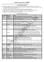
INPUT/OUTPUT FUNCTIONS
Terminals Function
Description
1-2-3
Power supply Input, 230VCA 50Hz (1-Neutral/2-Phase/3-GND)
4-5
Antenna
Connection, radio receiver board antenna (4-signal/5-screen).
6
COM
Common to control inputs.
7
Step-by-Step
Input, step-by-step button (N.O contact), operation presettable by Dip-
Switch 4.
8
PED
Input, PEDESTRIAL push-button (N.O. contact), opens for about 7 sec-
onds.
9
STOP
Input, STOP push-button (N.C. contact)
10
PHOT2
Input, connection to safety devices, N.C. contact (e.g. photocells)
This input is activated only during closure.
When the contact is open, the motor stops and immediately reverses its
movement (the gate opens).
11
PHOT1
Input, connection of safety devices, N.C. contact.
(e.g. photocells) Input activated in the opening and closing phases.
During opening: when the contact is open, the motor stops and when the
photocell is no longer darkened, the motor re-starts in the opening phase.
During closure: when the contact is open, the motor stops and when the
photocell is no longer darkened, the motor movement is reversed (the gate
opens).
12
COM
Common to photocell inputs.
13-14
COSTA
Input, sensitive safety edge
Resistive edge: Jumper “DAS” closed
Mechanical safety edge: Jumper “DAS” open
When the safety edge is activated, the gate movement is stopped and the
movement reversed for about 3 sec.
If the safety edge is not in use: “DAS” Jumper open and jumper between
terminals 13-14.
15-16
24 Vac
Output, 24VCA/0.5A max power supply of accessories
17-18
SCA/II°ch
Output, N.O. contact. It can be preset as open gate indicator light, 2
nd
radio
channel through DIP 1. Photocell power supply in FotoTest mode by DIP1:
OFF and DIP5:ON
19
SWO
Input, OPENING limit switch (N.C. contact).
20
SWC
Input, CLOSING limit switch (N.C. contact).
21
COM
Common, limit switch
22-23-24
Secondary
Connection, winding of secondary transformer, 24V
(22:12V/23:0V/24:12V)
25-26-27
Motor, 230V
Connection to motor (25:OPEN/26:COM/27:CLOSE)
25-28
Capacitor
Connection to capacitor
29-30
Flasher
Connection of flasher, 230VCA 40Wmax.
31-32
Primary
Connection, winding of primary transformer (31:L/32:N)
www.ga
ł
ecki.pl
Summary of Contents for CP.MS4
Page 23: ...w w w g a e c k i p l...


