19
TRANSMITTERS REMOTE LEARNING
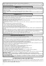
If an already memorised transmitter is available in the receiver it is possible to carry out remote radio learning (without needing to
access the control unit).
IMPORTANT: The procedure must be carried out with leaves in opening during TCA pause or with an open gate if the TCA
logic is OFF. The REM logic must be ON.
Proceed as follows:
1 Press the hidden key of the transmitter which is already memorised.
2 Press, within 5s, the key of the corresponding transmitter which is already memorised to associate to the new transmitter. The
flashing light will turn on.
3 Press within 10s the hidden key of the new transmitter.
4 Press, within 5s, the key of the new transmitter to associate to the channel chosen at point 2. The flashing light will turn off.
5 The receiver memorised the new transmitter and immediately exits from programming.
FUSES
F1: Accessory power supply safety fuse.
F2: General safety fuse
EMERGENCY BATTERY
An optional accessory is available for control unit power supply in case of absence of power.
The kit is made up of a battery charging board and two 12V rechargeable batteries, fixing clamps, screws and wiring.
For further information, refer to the instructions supplied with the accessory.
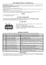
DIAGNOSTICS
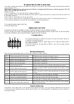
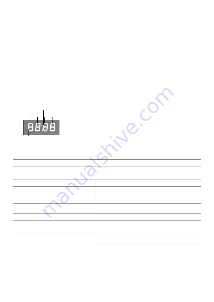
PHOT
SWC1
STOP
SWO1
SWO2
SWC2
PHOT-C
DAS
P.P.
PED OPEN CLOSE
One segment of the display is linked to each input. In the event of failure it switches on
according to the following scheme.
N.C. inputs are represented by the vertical segments. N.O. inputs are represented by
the horizontal segments.
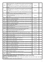
The control unit sees the message AMP1 or AMP2 in case of anti-crushing ammeter
sensor intervention.
ERROR MESSAGES
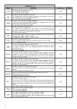
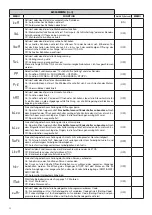
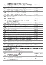
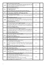
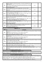
Some messages that are displayed in case of function anomalies are listed as follows:
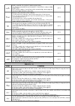
Amp1
Obstacle error motor 1/anti-crushing
Check presence of obstacles on motor 1 leaf run
Amp2
Obstacle error motor 2/anti-crushing
Check presence of obstacles on motor 2 leaf run
Err1
Motor 1 circuit checking error
Check motor 1 connections
Err2
Motor 2 circuit checking error
Check motor 2 connections
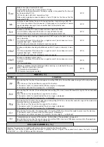
Err3
error/fault power circuit
Request technical assistance and eventually replace control unit.
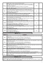
Err4
PHOTA photocell checking error
Check connections, PHOT A photocell alignment or presence of ob-
stacles.
Err5
PHOTC photocell checking error
Check connections, PHOTC photocell alignment or presence of ob-
stacles.
Err6
Error edge active (during autoset)
In autoset phase, the safety edge has intervened.
Err7
Error active stop (during autoset)
In autoset phase, the STOP input has intervened.
Err8
Error active input (during autoset)
In autoset phase a PP/Open/Close input has intervened.
thrm
Motor thermal protection intervention
Wait for motor cooling, in case reset does not take place, motor replace-
ment may be necessary
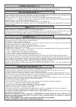
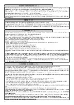
WASTE DISPOSAL
If the product must be dismantled, it must be disposed according to regulations in force regarding the differentiated waste disposal
and the recycling of components (metals, plastics, electric cables, etc..). For this operation it is advisable to call your installer or a
specialised company.

