


23
Symbols
“ALARM Ground Fault” LED
“ALARM Resistor Fault” LED
A
Alarm lamp H3
Alarm relay
Alarm relay operating mode
Areas of application
B
Bridge
C
cable glands
D
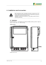
Dimensions
DIP switch
E
Earth-fault current
F
Factor 100
G
Guarantee
H
Housing door
I
Installations
- High-resistance earthed
Insulation fault
Intended use
M
Measuring current transformer
N
NER
Neutral earthing resistor (NER)
P
personnel
R
RESET key
Response value
S
Screws
Steel plate housing
T
Terminal strip
TEST key
Transparent window
Trip current
INDEX
Summary of Contents for RC48N-70-10 A
Page 4: ...Table of Contents 4 TGH1397en 11 2006...
Page 16: ...Installation and connection 16 TGH1397en 11 2006...
Page 20: ...Operation and configuration 20 TGH1397en 11 2006...
Page 24: ...INDEX 24 TGH1397en 11 2006...
Page 25: ......


