


19
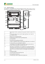
5.3 Setting the alarm relay operating mode
You can set the operating mode for the alarm relay via a bridge between the NC-NC contacts
on the RC48N-935:
5.4 Factory settings
Bridge open
N/O operation
Bridge closed
N/C operation (factory setting)
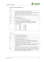
RC48N-70-10A
RC48N-70-50A
Filter:
DIP switch “Filter off / on”
on
on
Response range:
DIP switch “I
Δ
n x 10 / x 1”
x10 => 1...10 A
x1 => 0.1...1 A
Response delay t/s for alarm I
Δ
n
0.1 s (left-hand stop)
0.1 s (left-hand stop)
Residual current response value I
Δ
n/A
0.1 A (left-hand stop)
0.1 A (left-hand stop)
x factor 100 => 10 A
Response value for voltage drop U
Δ
/V at
the neutral earthing resistor NER
20 V (left-hand stop)
20 V (left-hand stop)
Operating principle of alarm relay:
NC-NC bridge
closed (N/C operation)
closed (N/C operation)
Response value for interruption of the neu-
tral earthing resistor (permanent setting)
> 2 k
Ω
> 2 k
Ω
Response delay for interruption of NER and
voltage drop at the NER
(permanent setting)
5 s
5 s
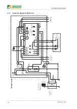
RC48N-935
A2
A1
U+
R
K
11
14 21
L
A1
T
A2
U-
12
22 24
GFA NRA
C1 C2
G1 G
NC NC
Summary of Contents for RC48N-70-10 A
Page 4: ...Table of Contents 4 TGH1397en 11 2006...
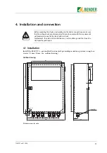
Page 16: ...Installation and connection 16 TGH1397en 11 2006...
Page 20: ...Operation and configuration 20 TGH1397en 11 2006...
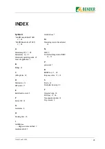
Page 24: ...INDEX 24 TGH1397en 11 2006...
Page 25: ......


