


Installation and connection
13
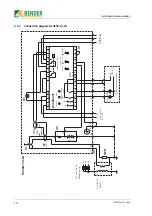
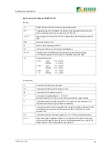
Key for connection diagram RC48N-70-10A
Devices
Connections
U1
RC48N-935 ground-fault and neutral-grounding monitor
U2
Coupling device CD1000 enables the voltage to be measured between the trans-
former neutral and earth up to a maximum of 1000 V AC.
-T2
Measuring current transformer W0-S15 to detect the current flowing through the
NER.
NER
Neutral earthing resistor.
S1
Master switch monitoring ON/OFF
H3
In the event of an alarm, alarm lamp H3 will light up
H1, H2
Optional, external indicator (alarm annunciator panel) with alarm lamps
H1 “ALARM Ground Fault” (GFA) and H2 “ALARM Resistor Fault” (NRA).
-X1
Connection terminals
T1, N1
rigid
2.5 ... 25 mm
2
flexible
4 ... 16 mm
2
1 x PE
rigid
0.5 ... 16 mm
2
flexible
0.5 ... 10 mm
2
2 x PE
rigid
0.2 ... 6 mm
2
1 ... 9
flexible
0.2 ... 4 mm
2
T1
Connection to transformer star point
N1
Connection to NER (neutral earthing resistor)
PE
Connections to PE (protective earth)
1, 2
Connection of supply voltage U
s
= 110 V DC
Recommended fuse: 6 A fuse as short-circuit protection for supply voltage
6
Connection of external alarm lamp GFA (H1). H1 lights up if the residual current
response value and the response time are exceeded.
7
Connection of external alarm lamp NRA (H2). H2 lights up if the voltage across the
neutral earthing resistor exceeds the response value or if the NER’s resistance
exceeds 2 K
Ω
.
8, 9
Connection of external auxiliary supply (e.g. 110 V DC) for external alarm lamps
3, 4, 5
Alarm relays (free changeover contacts) trip in the event of an alarm. Alarm relay
can be used to trigger an acoustic signal or switching operation. Set using NC-NC
bridge, either N/C or N/O operation can be selected.
Summary of Contents for RC48N-70-10 A
Page 4: ...Table of Contents 4 TGH1397en 11 2006...
Page 16: ...Installation and connection 16 TGH1397en 11 2006...
Page 20: ...Operation and configuration 20 TGH1397en 11 2006...
Page 24: ...INDEX 24 TGH1397en 11 2006...
Page 25: ......


