


Operation and configuration
18
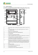
5.2 Operating elements RC48N-70-50A
1
Master switch S1: Monitoring ON/OFF
2
Press the TEST key to initiate the following sequence: A test residual current is simulated and
once the response time has elapsed, an alarm is recognised; which causes the alarm relay to
switch and the “ALARM Ground Fault” LED and alarm lamp H3 to light up. The alarm message is
stored.
3
Press the RESET key to delete alarm messages
4
ON LED (green) lights up to indicate that the RC48N is in operation.
5
The “ALARM Ground Fault” LED (red) lights up if the residual current response value and the
response time are exceeded.
6
The “ALARM Resistor Fault” LED (red) lights up if the voltage across the neutral earthing resistor
exceeds the response value or if the NER’s resistance exceeds 2 K
Ω
.
7
DIP switch “Filter OFF/ON”: Bandpass filter 50 ... 60 Hz.
When the bandpass filter is switched on, only the narrow-band 50 ... 60 Hz components of the
residual current are detected. This function can be used to prevent erroneous tripping as a
result of harmonics and transient components in the residual current.
8
The second measuring current transformer generates a measurement signal reduced by a fac-
tor of 100. Set this DIP switch to x1. The response value set at the potentiometer (0.1... 1 A) is
multiplied by the factor x100.The response range is 10 A ... 100 A.
9
For setting the response delay t/s for the residual current measurement from 0.1 to 2 seconds.
10
For setting the residual current response value from 10 A to 100 A. Example: On the device,
select 0.1 A for an actual response value of 10 A.
11
For setting the response value for voltages across the neutral earthing resistor from
20 to 400 V.
12
In the event of an alarm, alarm lamp H3 will light up.
1
2
7
6
5
4
3
9
8
U
D
/ V
RC48N
A1 A1
A2
11 12 14
21 22 24
T
R
NRA C2 U+
G1 G
k
l
NC NC
GFA C1
U-
A2
t / s
I
D
n
/A
20
200
400
ALARM
Ground
Fault
ALARM
Resistor
Fault
TEST
RESET
ON
Filt
er off / on
I
D
n x 10 / x 1
V
D
MONITOR
I
D
n
W
0,1
0,5
1
0,1
1
2
ON
OFF
ALARM
10
11
12
S1
H3
U1
x100
Summary of Contents for RC48N-70-10 A
Page 4: ...Table of Contents 4 TGH1397en 11 2006...
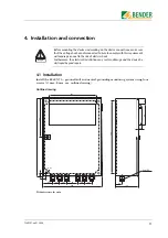
Page 16: ...Installation and connection 16 TGH1397en 11 2006...
Page 20: ...Operation and configuration 20 TGH1397en 11 2006...
Page 24: ...INDEX 24 TGH1397en 11 2006...
Page 25: ......


