


17
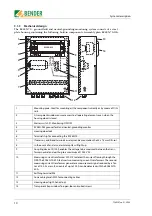
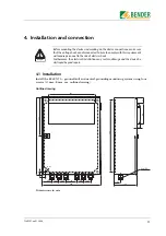
5. Operation and configuration
5.1 Operating elements RC48N-70-10A
1
Master switch S1: Monitoring ON/OFF
2
Press the TEST key to initiate the following sequence: A test residual current is simulated and
once the response time has elapsed, an alarm is recognised; which causes the alarm relay to
switch and the “ALARM Ground Fault” LED and alarm lamp H3 to light up. The alarm message is
stored.
3
Press the RESET key to delete alarm messages
4
ON LED (green) lights up to indicate that the RC48N is in operation.
5
The “ALARM Ground Fault” LED (red) lights up if the residual current response value and the
response time are exceeded.
6
The “ALARM Resistor Fault” LED (red) lights up if the voltage across the neutral earthing resistor
exceeds the response value or if the NER’s resistance exceeds 2 K
Ω
..
7
DIP switch “Filter OFF/ON”: Bandpass filter 50 ... 60 Hz.
When the bandpass filter is switched on, only the narrow-band 50 ... 60 Hz components of the
residual current are detected. This function can be used to prevent erroneous tripping as a
result of harmonics and transient components in the residual current.
8
DIP switch “I
Δ
n x 10 / x 1”: For configuring the setting range of the residual current response
value I
Δ
n/A
x 1:
0.1 A ... 1 A
x 10:
1 A ... 10 A
9
For setting the response delay t/s for the residual current measurement from 0.1 to 2 seconds.
10
For setting the residual current response value from 0.1 A to 1 A and 1 A to 10 A respectively.
11
For setting the response value for voltages across the neutral earthing resistor from
20 to 400 V.
12
In the event of an alarm, alarm lamp H3 will light up.
1
2
7
6
5
4
3
9
8
U
D
/ V
RC48N
A1 A1
A2
11 12 14
21 22 24
T
R
NRA C2 U+
G1 G
k
l
NC NC
GFA C1
U-
A2
t / s
I
D
n
/A
20
200
400
ALARM
Ground
Fault
ALARM
Resistor
Fault
TEST
RESET
ON
Filt
er off / on
I
D
n x 10 / x 1
V
D
MONITOR
I
D
n
W
0,1
0,5
1
0,1
1
2
ON
OFF
ALARM
10
11
12
S1
H3
U1
Summary of Contents for RC48N-70-10 A
Page 4: ...Table of Contents 4 TGH1397en 11 2006...
Page 16: ...Installation and connection 16 TGH1397en 11 2006...
Page 20: ...Operation and configuration 20 TGH1397en 11 2006...
Page 24: ...INDEX 24 TGH1397en 11 2006...
Page 25: ......


