


11
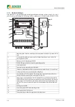
4. Installation and connection
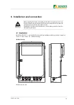
4.1 Installation
Install the RC48N-70... ground-fault and neutral-grounding monitoring system using four
screws (
∅
max. 8 mm, see outline drawing).
Outline drawing
Dimensions in mm
Before mounting the device and working on the device connections, make sure
that the voltage has been disconnected. Failure to comply with this requirement
will expose personnel to the risk of electric shock.
Furthermore, the electrical installation may sustain damage and the device be
destroyed beyond repair.
Danger
!
20
F
8,7
20
200
400
20
360
234
98
32
20
300
46
120
6 x M20
50
35
35
60
35
35
Summary of Contents for RC48N-70-10 A
Page 4: ...Table of Contents 4 TGH1397en 11 2006...
Page 16: ...Installation and connection 16 TGH1397en 11 2006...
Page 20: ...Operation and configuration 20 TGH1397en 11 2006...
Page 24: ...INDEX 24 TGH1397en 11 2006...
Page 25: ......


