


Maintenance, troubleshooting, messages
75
VMD460-NA_D00001_05_M_XXEN/01.2020
At least one undervoltage limit value must have been set because a measured value of
0 V is simulated at L
1-N
for the duration of the self test. The test continues until the dis-
connection time for "Undervoltage" t
(OFF)
has elapsed but no more than two minutes.
•
During the self test, the time is measured that passes until the disconnection command
is given by the VMD460-NA (
t
(OFF) DEVICE
).
•
When contact monitoring is activated for K1, the time until the interface switch K1 has
actually disconnected is additionally measured (
t
(OFF) TOT
).
The times measured will be indicated on the display as an alarm for 10 seconds. In ad-
dition, the times can be viewed in the
Menu: 1. Alarm/measured values
under channel 16
(t
(OFF) TOT
) and channel 17 (t
(OFF) DEVICE
).
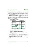
Fig. 7.1: Comments on the timing diagram:
•
Times (*) are measured during the self test
– t
(OFF) DEVICE
is the disconnection time of the VMD460-NA;
– t
(OFF) TOT
will only be measured when contact monitoring is activated by K1
and has been connected..
•
t
interface switch 1
= t
(OFF) TOT
- t
(OFF) DEVICE
•
All standards (with the exception of CEI 0-21): When disconnecting the generating plant
the redundancy (K2) switches to the first interface switch K1 with a delay of 50 ms. After
reconnection, K2 closes first and K1 with a delay of 50 ms. In this way, the redundant
interface switch is protected, as it always switches free of load.
•
As soon as the system voltage exceeds the switching threshold again, the start-up delay
t
(ON)
begins.
t
off
t
off
U<
t
on
Relais
K1
* t
off GERAET
* t
off(GES)
t
Kuppelschalter 1
Rückmelde-
kontakt
D1
50 ms
Relais
K2
Rückmelde-
kontakt
D2
Redundanz (Kuppelschalter 2)
t
Kuppelschalter 2
Diagramm Schaltzeiten: Relais und Rückmeldekontakte
Netzspannung
t
Kuppelschalter 1
t
Kuppelschalter 2
50 ms


