


Installation, connection and commissioning
35
VMD460-NA_D00001_05_M_XXEN/01.2020
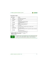
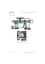
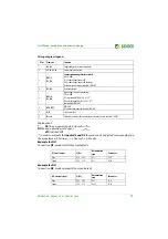
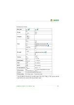
Wiring diagram legend
Explanations :
*
NC
(in non-operating state closed)
NO
(in non-operating state open)
off
(switched off)
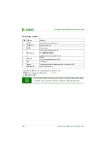
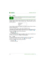
** In order to evaluate the
inputs D3 and D4
the mode can be adjusted correspondingly in
the menu (menu: 3. Settings --> 1. General --> 4. Mode) :
Example for NO
:
Connection
D3
, mode: local (D4 not evaluated)
Example for NO
:
Connection
D4
, mode: external (D3 not evaluated)
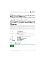
No.
Element
Function
1
A1, A2
Supply voltage
U
s
(see ordering details)
2
L1, L2, L3, N
Power supply connection
3
DG1/2,
D1, D2
Contact monitoring interface switch
DG1/2: GND
D1: Feedback signal contact K1
D2: Feedback signal contact K2 (backup)
(feedback signal contact optionally NC/NO/off)*
4
K1, K2
Relay connections
5
DG3/4,
D3, D4
Digital inputs (external monitoring)
DG3/4: GND
D3: local control (CEI 0-21 8.6.2.1.1)**
D4: external signal (CEI 0-21 8.6.2.1.2)**
(optionally NC/NO/off)*
6
RTG, RT1
RTG: GND
RT1: remote trip input
(optionally NC/NO/off)*
7
A, B
Service interface
8
R
on/off
Activate or deactivate the terminating resistor of the service interface (120
Ω
)
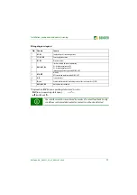
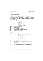
D3: local control
f [Hz]
Disconnection
time
Parameter
Open
49.5…50.5
0.1 s
81.S1
Closed
47.5…51.5
0.1 s
81.S2
D4: external signal
f [Hz]
Disconnection
time
Parameter
Open
49.5…50.5
0.1 s
81.S1
Closed
47.5…51.5
4 s; 1 s
81.S2


