


Installation, connection and commissioning
36
VMD460-NA_D00001_05_M_XXEN/01.2020
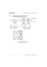
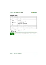
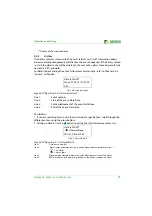
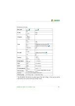
4.8.6
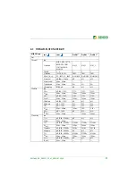
Details regarding the digital inputs (D1…D4, RT1)
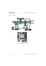
Fig. 4.7: Block diagram (simplified representation)
In the event of a fault in interface switch 1 (K1), the contact monitoring
causes the backup relay (K2) to switch.
low : < 4 V DC
high : > 6 V DC
U
max
= 30 V DC
D1
Dx
GND
12V
R1
DC
Source
I < 5 mA
Open
Collector
DGx
µC
Relais
Kontakt
Q1
V1
24
1
2
Dx:
D1, D2, D3, D4, RT1
DGx: DG1/2, DG3/4, RTG


