


Installation, connection and commissioning
24
VMD460-NA_D00001_05_M_XXEN/01.2020
4.3 Installation instructions
The devices are suitable for the following installation methods:
•
Standard distribution panels in accordance with DIN 43871 or quick DIN rail mounting
in accordance with IEC 60715
•
Screw mounting using M4 screws
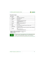
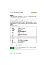
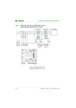
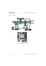
4.4 Schematic diagram
Fig. 4.1: Schematic diagram of a central NS protection with interface switches
Danger of electric shock!
Make sure that the installation area is
disconnected from any electrical
source .
Consider the data on
the rated voltage and supply voltage
as specified
in the technical data!
The
length of the connecting cable
of the device connections DG1/2,
D1, D2, DG3/4, D3, D4, RTG and RT1 is to be limited to
3 m
.
In order to ensure the proper functioning of the VMD460-NA after a pow-
er failure, an
external UPS
is to be used.
In this case, the following exception applies:
If a delay or disconnection time smaller than the bridging time is config-
ured for voltage drop protection (U< or U<<), no external UPS must be
provided for the supply voltage. The bridging time is 600 ms at a supply
voltage Us = 230 V.
This applies, for example, to the following default profiles:
VDE-AR-N 4105:2018-11; VDE-AR-N 4105:2011-08; G59/3, G83/2; G59/2;
VDE-AR-N 4110:2018-11 Profile 4; BDEW guideline; 0126; CEI 0-21
DANGER
G
VMD460
VMD460


