2122.6-0000010 OM
229
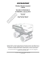
Figure 6.12.1 – RLL electronic control syste
m
cables
To t
h
e L
L
p
o
siti
on se
n-
sor (bl
ack so
ck
et co
n-
nect
or)
Nu
mber
s of
pin connec
tors,
not sho
w
n in the figur
e, are
drawn on c
a
se-s
h
ape
d
p
a
rts
of
co
n
n
ector
s
To t
h
e u
p
lif
t sol
e
noi
d-o
p
erat
ed
valve (yell
o
w so
cket co
nn
ect
or)
To t
h
e lo
weri
ng
solen
o
id
-op
e
rat
e
d
valve (
b
lack s
o
c
ket co
nne
ctor
)
To t
h
e le
ft
remot
e
pa
nel
Joint
s
cab -
trans
m
issi
on
To t
h
e le
ft f
o
rce
sensor
(grey s
o
cke
t co
nnec
tor)
To t
h
e rig
h
t
forc
e sens
o
r
(grey s
o
cke
t co
nnec
tor)
To t
h
e rig
h
t
remot
e
pa
nel
To t
h
e elec
tro
n
ic
unit
To t
h
e
main c
o
n
-
trol pa
nel
To t
h
e f
u
se
block
Po
w
e
r “m
in
u
s
”
(“
load
”
)
https://tractormanualz.com/