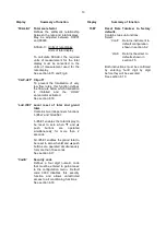
Step 8
Calibrate the rate display
Select calibration of the rate display
using an external current source 'CAL'
from the configuration menu and press
P
The BA354E will request a 4mA
input by displaying 'ZEro'. Set the
input current to 4.0000mA and press
P
which will reveal the existing rate
display with one digit flashing. Using
the ▼ and ▲ buttons to adjust each
digit and the
P
push button to move
control between digits, enter the
required zero display of 0000. Press
E
to enter this calibration figure and
return the instrument to the 'ZEro'
prompt.
Press the
▲
push button
and the
instrument will request a 20mA input by
displaying '5PAn'. Set the input
current to 20.0000mA and press
P
which will reveal the existing rate
display at 20mA. Using the ▼, ▲ and
P
push buttons enter the required
display of 1100.0
Press
E
to enter this calibration figure
and return the instrument to the '5PAn'
'prompt' and again to return to the 'CAL'
prompt in the configuration menu.
Step 9
Define the timebase
In this example the rate display
represents flow per minute so it is
necessary to set the instrument
timebase to 60. This will divide the rate
display by 60 to provide the correct
total display.
Select 't-bA5E' from the main menu and
press
P
to reveal the current setting.
Using the ▼ and ▲ push buttons select
'tb - 60' and then return to the
configuration menu by pressing
E
.
Step 10 Define the totaliser scaling factor
In this example the rate display is in
litres per minute but the total display is
required in cubic metres:
5CALE-t
= Units of rate display
Units of total display
There are 1,000 litres in a cubic metre
thus:
= litres
cubic metres
= 1 litre
1/(1000) litres
5CALE-t = 1000
From the configuration menu select
'5CALE-t' and press
P
to reveal the
current five digit dividing factor. Using
the ▼ and ▲ buttons to adjust the
flashing digit, and the
P
button to
transfer control between digits.
The position of the decimal point is
adjusted by repeatedly pressing the
P
button until the decimal point flashes.
The decimal point can then be moved
to the required position by operating the
▼ or ▲ button. When set to 1000.0
press
E
to return to the ‘5CALE-t’
prompt in the configuration menu.
Step 11 Define totalisation clip-off
In this example totalisation is to be
inhibited below 1% (11 litres / minute)
of maximum flow. To define this cut-off
point select 'CLiP-oFF' from the
configuration menu and press
P
which
will reveal the existing setting. Using
the ▼, ▲ and
P
push buttons enter the
required clip-off of 11.0 and then return
to the 'CLiP-oFF' prompt in the
configuration menu by pressing
E
.
Step 12 Local reset of total display
This example requires that the total
display resets to zero when the ▼ and
▲
buttons
are
operated
simultaneously. To enable this function
select ‘LoC.r5Et’ from the configuration
menu and press
P
followed by ▼ or ▲
to select ‘t-rE5Et’. Operating the
P
button will reveal if the function is ‘on’
or ‘off’. Using the ▼ or ▲ button
toggle the display to ‘on’ and return to
the configuration menu by pressing
E
twice.
25


