4. SYSTEM DESIGN FOR HAZARDOUS AREA
4.1 Flow transmitter loops
A BA354E Rate Totaliser may be connected in
series with almost any intrinsically safe 4/20mA
flow loop and calibrated to display the rate of flow
and total flow. There are three basic design
requirements:
1.
The intrinsic safety output parameters of the
4/20mA loop, which are defined by the Zener
barrier or galvanic isolator powering the loop,
must be equal to or less than:
Uo
=
30V dc
Io
=
200mA
Po
=
0.84W
2.
The maximum permitted cable capacitance of the
loop must be reduced by 13nF. The maximum
permitted cable inductance is not reduced by the
inclusion of the BA354E.
3.
The loop must be able to tolerate the additional
1.2V required to operate the Rate Totaliser.
When fitted with an optional backlight this
increases to 5.0V if the backlight is loop powered.
See 10.3.1
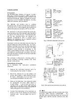
Figs 2a and 2b illustrates typical applications in
which a Rate Totaliser is connected in series with a
2-wire flow transmitter powered by a Zener barrier
and alternatively by a galvanic isolator.
Fig 2a Loop powered by a Zener barrier
Fig 2b Loop powered by a galvanic isolator
4.2 Resetting the total display to zero
The BA354E total display may be reset to zero by
momentarily connecting the reset terminals RS1
and RS2 together with a resistance of less than
1kΩ. Within the hazardous area in which the
BA354E is located this may be achieved with a
manually activated industrial push button as shown
in Fig 3b.
The push button switch and the wiring connecting it
to the Rate Totaliser must comply with the
requirements for simple apparatus specified in
Clause 5.7 of EN60079-11. i.e. be able to
withstand a 500V rms insulation test for one
minute. The switch must comply with electrostatic
requirements specified by Clause 7 of EN60079-0
and material composition defined in Clause 8.
If it is required to reset the total display from the
safe area a Zener barrier, galvanic isolator or
intrinsically safe relay must be used to transfer the
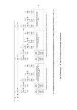
contact closure into the hazardous area. Fig 3a
shows how a single channel positive polarity Zener
barrier may be used.
Note:
The negative reset terminal RS2 is internally
connected to the negative 4/20mA input
terminal 3.
4.3 Remote indication
A BA354E may be driven via an intrinsically safe
interface from a 4/20mA safe area signal to provide
a remote indication of rate and total flow within a
hazardous area. The type of interface is not
critical, either a Zener barrier or a galvanic isolator
may be used, providing that Ui, Ii and Pi of the
BA354E 4/20mA input are not exceeded.
If one side of the 4/20mA current loop may be
earthed, a single channel Zener barrier provides
the lowest cost protection. If the 4/20mA signal is
not isolated, then two Zener barriers, a two
channel Zener barrier or a galvanic isolator must
be used.
When the hazard is a IIC gas and two single
channel Zener barriers or a two channel Zener
barrier are used, only one barrier or channel may
be a 28V 93mA device. A 10V 50
or diode
return barrier may be used for the second channel
to form a safe combination.
Again it is necessary to ensure that the voltage
capability of the 4/20mA signal is sufficient to drive
the Rate Totaliser plus the voltage drop introduced
by the intrinsically safe interface. Figs 3a, 3b and
3c show the alternative circuits which may be
used.
7


