background image

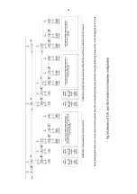
Fig 16  Loop powered backlight

The   input   intrinsic   safety   parameters   of   the
combined   Rate   Totaliser   and   backlight   are   the
same   as for  the  Rate  Totaliser   alone.    The  EC-
Type   Examination   Certificate   states   that   for
intrinsic   safety   considerations,   under   fault
conditions the output voltage, current and power of
the   combined   Rate   Totaliser   and   backlight
terminals 12 & 3 will not exceed those specified by
clause 5.7 of EN 60079-11 for  

simple apparatus,

w

hich simplifies system design and documentation.

Providing   the   increased   voltage   drop   can   be
tolerated   the   intrinsic   safety   and   system   design
described   in   sections   3   and   4   of   this   manual
remain valid with the backlight loop powered.    

10.3.2  Separately powering the backlight

The optional backlight may also be powered from a
separate safe area power supply via an intrinsically
safe interface as shown in Fig 17.    

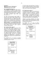
Fig 17  Separately powered backlight

When   separately   powered   the   backlight   is   a
current sink drawing a constant current when the

supply is equal to or greater the minimum specified
voltage.     Below this supply  voltage  the  backlight
continues to function but with reduced brilliance.

                       Current      Minimum voltage

35mA

11V

Any certified Zener barrier or galvanic isolator may
be used, providing the output parameters do not
exceed:

Uo

=

30V dc 

Io

=

200mA

Po

=

0.84W

The following equivalent internal capacitance and
inductance between terminals 12 & 14 should be
subtracted from Co and Lo of the intrinsically safe
interface   powering   the   backlight   to   provide   the
maximum permissible cable parameters. 

Ci

=

13nF

Li

=

8µH

35

Summary of Contents for BA354E

Page 1: ...Issue 5 14th October 2015 BA354E Intrinsically safe 4 20mA loop powered field mounting Rate Totaliser Issue 5 ...

Page 2: ...e Adding break points to a new Rate Totaliser 7 2 Calibration using internal reference 7 2 1 Example Adding break points to a new Rate Totaliser 7 3 Error messages 7 4 Under and over range 7 5 Default configuration 8 Calibration Examples 8 1 Using an external current source 8 2 Using the internal reference 9 Maintenance 9 1 Fault finding during commissioning 9 2 Fault finding after commissioning 9...

Page 3: ...ument The voltage developed across R1 which is proportional to the 4 20mA input current provides the input signal for the analogue to digital converter Each time a 4 20mA current is applied to the instrument initialisation is performed After a short delay the following display sequence occurs which takes about twelve seconds All segments of the display are activated Loading message displayed Confi...

Page 4: ... clear the grand total and Gt CLrd will be displayed to confirm the operation The instrument will then automatically return to the operating mode Selectable function in configuration menu See section 6 17 Note Totalisation will continue until CLr no or CLr YE5 are displayed Resets the total display to zero when these two push buttons are operated simultaneously Selectable function in the configura...

Page 5: ...ly exist for a short time Be used with gases in groups Group A propane Group B ethylene Group C hydrogen In gases that may be used with equipment having a temperature classification of T1 450o C T2 300o C T3 200o C T4 135o C T5 100o C At ambient temperatures between 40 and 70o C CAUTION installation in Zone 0 When installed in a Zone 0 potentially explosive atmosphere requiring EPL Ga apparatus th...

Page 6: ...osure into the hazardous area Almost any intrinsically safe relay with certification permitting the contacts to be connected to equipment in the hazardous area may be used Alternatively a positive polarity Zener barrier with intrinsic safety parameters equal to or less than the input safety parameters of the reset terminals may be used as shown in Fig 3A The total resistance of the barrier switch ...

Page 7: ... simple apparatus specified in Clause 5 7 of EN60079 11 i e be able to withstand a 500V rms insulation test for one minute The switch must comply with electrostatic requirements specified by Clause 7 of EN60079 0 and material composition defined in Clause 8 If it is required to reset the total display from the safe area a Zener barrier galvanic isolator or intrinsically safe relay must be used to ...

Page 8: ...rth Also illustrates resetting from safe area Fig 3b Two Zener barrier channels are required if the 4 20mA current loop can t be earthed at the barrier busbar Also shows optional resetting from hazardous area Fig 3c Galvanic isolator can be used with any 4 20mA current loop 8 ...

Page 9: ...enclosure If this enclosure is not bolted to an earthed post or structure the earth terminal should be connected to the plant potential equalising conductor The enclosure is fitted with a bonding plate to ensure electrical continuity between the three conduit cable entries 5 2 Installation Procedure Fig 4 illustrates the instrument installation procedure 1 Remove the instrument terminal cover by u...

Page 10: ...arised using the square root extractor or the 16 segment lineariser which are selectable in the instrument s FunC sub menu The rate display may then be calibrated using the CAL or 5Et functions to show the flow rate in the required linear engineering units Both the zero display at 4mA and the span display at 20mA are adjustable although for unidirectional flow application the display at 4mA is usu...

Page 11: ...e entered using the and push buttons and the P button to move control to the next digit When the correct four digit code has been entered pressing E will cause the first parameter FunC to be displayed If the code is incorrect or a button is not pressed within twenty seconds the Rate Totaliser will automatically return to the display mode Once within the configuration menu the required parameter ca...

Page 12: ... on or oFF See section 6 8 dP Decimal points Positions the decimal point in the rAtE and totAL displays See section 6 9 Display Summary of function CAL Calibration of the rate display using an external current source Enables the zero and span of the rate display to be adjusted using an external current source such as a calibrator When used with an accurate traceable calibrator this is the preferre...

Page 13: ...and Gt rE5Et t rE5Et enables the total display to be reset to zero when and push buttons are operated simultaneously for more than 2 seconds Gt rE5Et enables the grand total to be reset to zero when E and push buttons are operated simultaneously for more than 10 seconds See section 6 17 CodE Security code Defines a four digit numeric code that must be entered to gain access to the configuration me...

Page 14: ...14 ...

Page 15: ...earity with bi directional flow Use of the lineariser is described in section 7 of this instruction manual 6 5 Display resolution rE5n This function defines the resolution of the least significant display digit of the rate display Decreasing the display resolution can improve the readability of a noisy signal Select rE5n from the menu and press P which will reveal the current display resolution To...

Page 16: ...ay and identify the lower display variable but on the larger upper display The position of the decimal point can be positioned in the same way by operating the and push buttons when set as required enter the setting and return to the conditioning menu by operating the E button 6 10 Calibration of the rate display using an external current source CAL This function enables the zero and span of the r...

Page 17: ...as been activated see section 6 17 To zero the grand total from within the configuration menu select Clr Gtot and press P which will cause the instrument to display Clr no Press the or button until CLr YES is displayed and then press P which will result in a 0000 prompt Using the and buttons and the P button to move to the next digit enter 5urE digit by digit to confirm the instruction Pressing E ...

Page 18: ... flow rates which over long periods may result in significant totalisation errors the BA354E rate display can be conditioned to stop totalisation when the flow rate falls below a specified clip off threshold Clip off is an absolute value for bi direction flow systems it inhibits totalisation for flow rates between clip off and clip off Clip off is shown in the same units as the instruments rate di...

Page 19: ... Rate Totaliser is returned to the display mode Please contact BEKA associates sales department if the security code is lost 6 19 Reset to factory defaults r5Et This function enables the Rate Totaliser and the lineariser to be quickly returned to the factory default configurations shown in sections 6 2 and 7 5 To reset the Rate Totaliser or lineariser select r5Et from the configuration menu and pr...

Page 20: ...Lineariser calibration using an external current source This method allows direct calibration of the lineariser with an external current source and is the preferred method when traceability is required If the exact system non linearity is unknown this method also allows direct calibration from the variable to be displayed The number of break point required should first be entered using the Add and...

Page 21: ...21 ...

Page 22: ...ollowing break point 7 1 1 Example Adding break points to a new Rate Totaliser When adding break points to a new Rate Totaliser or to a lineariser following resetting to the factory defaults using the LtAb function described in section 6 19 each additional break point should be added before the highest existing breakpoint The first additional break point should be added before the default break po...

Page 23: ...he E button The corresponding rate display at each of the break points can now be defined using the diSP sub function Using the and buttons select the diSP sub function and press P which will reveal the starting point for the first break point 0 n where n is the total number of break points entered Press P and use the and buttons and the P button to move between digits to enter the required rate d...

Page 24: ...her the root extractor or the lineariser are required The standard linear relationship should therefore be selected With FunC displayed press P which will reveal the existing function Using the or button select 5td Press E to enter this selection and return to the FunC prompt in the configuration menu Step 4 Define function of P push button Select C P from the configuration menu and press P to rev...

Page 25: ...r In this example the rate display is in litres per minute but the total display is required in cubic metres 5CALE t Units of rate display Units of total display There are 1 000 litres in a cubic metre thus litres cubic metres 1 litre 1 1000 litres 5CALE t 1000 From the configuration menu select 5CALE t and press P to reveal the current five digit dividing factor Using the and buttons to adjust th...

Page 26: ...n and total flow in cubic metres with a resolution of 0 1 cubic metres Total is to be shown on the upper large display and rate on the lower smaller display Totalisation is to occur for flow rates between 1 and 100 of maximum flow A security code of 1209 is required In the operating mode the BA354E is required to display the input current as a percentage of span when the P push button is operated ...

Page 27: ...ilure Symptom Cause Check No display and no voltage between terminals 1 3 No power supply Confirm that a 4 20mA current is flowing in the loop Unstable rate display 4 20mA current is noisy or the flow signal is unstable Eliminate source of electrical noise Reduce resolution of the rate display to mask flow noise Unable to access configuration menu Incorrect security code Enter the correct security...

Page 28: ... can accommodate 1 row of 9 alphanumeric characters 10mm high or 1 row of 11 alphanumeric characters 7mm high or 2 rows of 18 alphanumeric characters 5mm high 10 2 Alarms CAUTION These alarms outputs should not be used for critical safety applications such as an emergency shut down system The BA354E Rate Totaliser can be supplied with factory fitted dual alarms with solid state single pole outputs...

Page 29: ... EN 60079 11 for simple apparatus This simplifies system documentation and allows the alarm output terminals 8 9 and 10 11 to be connected to almost any intrinsically safe circuit protected by a Zener barrier or galvanic isolator providing the output parameters of the circuit do not exceed Uo 30V dc Io 200mA Po 0 84W The maximum equivalent capacitance and inductance between each set of alarm termi...

Page 30: ...30 ...

Page 31: ...ated when the selected display rate or total equals the setpoint See section 10 2 6 Hi Lo Alarm function Defines the alarm function as High or Low See section 10 2 7 no nC Normally open or normally closed output Sets the alarm output open or closed in the non alarm condition See section 10 2 8 H5tr Hysteresis Adjusts the alarm hysteresis Only available on rate alarms See section 10 2 9 dELA Alarm ...

Page 32: ...by pressing the or button followed by the E button to return to the alarm menu 10 2 8 Alarm output status no nC Configures the solid state alarm output to be open no or to be closed nC in the non alarm condition When deciding which is required care should be taken to ensure that the alarm output is fail safe as illustrated in Fig 10 no Alarm output open in non alarm condition nC Alarm output close...

Page 33: ...e rate or total display depending upon which has caused the alarm alternates between the numerical value and the alarm reference ALr1 or ALr2 when the alarm output is activated If both alarm outputs are activated by one variable the display alternates between the numerical value and Alr1 2 To enable or disable the function select FL5H from the alarm menu and press P which will reveal the current s...

Page 34: ...h the other setpoint may be selected or the Rate Totaliser may be returned to the display mode by pressing E again Notes 1 With the Rate Totaliser in the display mode direct access to the alarm setpoints is only available when the AC5P menu is enabled see section 10 2 13 2 While the alarm setpoints are being adjusted from the display mode totalisation is suspended any flow occurring during this ti...

Page 35: ...d 10 3 2 Separately powering the backlight The optional backlight may also be powered from a separate safe area power supply via an intrinsically safe interface as shown in Fig 17 Fig 17 Separately powered backlight When separately powered the backlight is a current sink drawing a constant current when the supply is equal to or greater the minimum specified voltage Below this supply voltage the ba...

Page 36: ... removing the enclosure control cover 10 5 Pipe mounting kits Two pipe mounting kits are available for securing the BA304E and BA324E to a horizontal or vertical pipe BA392D Stainless steel bracket secured by two worm drive hose clips Will clamp to any vertical or horizontal pipe with an outside diameter between 60 and 80mm BA393 Heavy duty stainless steel bracket secured by a single V bolt Will c...

Page 37: ... with dust in subdivisions IIIA combustible flyings IIIB non conductive dust IIIC conductive dust Having a Minimum Ignition Temperature of Dust cloud 120 C Dust layer on the Rate Totaliser 155 C up to 5mm thick Dust layer on the Rate Totaliser over 5mm thick Refer to EN 61241 14 At an ambient temperature between 40 and 70 C Note The specified operating temperature of the BA354E is 20 to 70ºC At te...

Page 38: ...and dust intrinsic safety parameters are identical to the ATEX safety parameters described in the main section and Appendix 1 of this manual The IECEx certificate may be downloaded from www beka co uk www iecex com or requested from the BEKA sales office A2 2 Installation The IECEx and ATEX certificates specify identical safety parameters and installation requirements for both approvals as defined...

Page 39: ...of Intrinsically Safe Systems for Hazardous Classified Locations and with the National Electrical Code ANSI NFPA70 Installations in Canada must comply with the Canadian Electrical Code C22 2 The BA354E has a T5 rating at ambient temperatures up to 70ºC and may be used with the following gases and dusts Intrinsic Safety Division 1 or 2 Class I Group A B Group C Group D Class II Group E F G Class II...

Page 40: ...40 ...

Page 41: ...41 ...

Page 42: ...42 ...

Page 43: ...43 ...

Page 44: ...44 ...

Page 45: ...45 ...

Page 46: ...46 ...

Page 47: ...47 ...

Page 48: ...48 ...

Page 49: ...49 ...

Page 50: ...50 ...

Reviews: