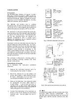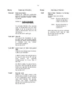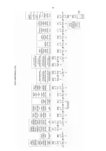
Full Description of Push Button Functions
P
While this button is pushed the rate
display will show the input current in
mA, or as a percentage of the
instrument span depending upon how
the instrument has been configured.
When the button is released the normal
display in engineering units will return.
The function of this push button is
modified when optional alarms are fitted
to the instrument.
▼
While this button is pushed the
instrument will show the calibrated rate
display with 4mA
*
input - usually zero
for flow applications. When the button
is released the flow rate will again be
displayed.
▲
While this button is pushed the
instrument will show the calibrated rate
display with 20mA
*
input. When the
button is released the flow rate will
again be displayed.
E
While this button is pushed the Rate
Totaliser will display the time in hours,
minutes and seconds since the
instrument was powered or the total
display was reset. The elapsed time is
not saved when power is removed.
E+▼
While these buttons are pushed the
total display will show the least
significant eight digits of the grand total,
and the grand total annunciator will be
activated.
E
+▲
While these two buttons are pushed the
total display will show the most
significant eight digits of the grand total
and the grand total annunciator will be
activated.
After the two buttons have been pushed
for ten seconds ‘CLr no’ with the ‘no’
flashing will be displayed. If no action
is required, pressing
E
will return the
instrument to the operating mode.
Operating the ▼ or ▲ button will toggle
the display to ‘CLr YES’ with ‘YES’
flashing, operating the
E
button will then
clear the grand total and ‘Gt CLrd’ will
be displayed to confirm the operation.
The instrument will then automatically
return to the operating mode.
Selectable function in configuration
menu. See section 6.17
Note:
Totalisation will continue until
‘CLr no’ or ‘CLr YE5’ are displayed.
▼
+
▲
Resets the total display to zero
when these two push buttons are
operated simultaneously. Selectable
function in the configuration menu.
See section 6.17
P +
▼
Rate Totaliser displays firmware
version.
P + ▲
Provides direct access to the alarm
setpoints when optional alarms are
fitted to the Rate Totaliser and the
‘AC5P’ access setpoints in display
mode function has been enabled.
See section 10.2.13
P+E
Provides access to the configuration
menu via optional security code.
Note:
*
If the Rate Totaliser has been
calibrated
using the CAL function,
calibration
points may not be 4 and
20mA.
2.2 Displays
The BA354E has two digital displays and
associated annunciators, plus a flow indicator as
shown on page 1.
Lower
Shows the flow rate on the five digit
display
plus sign 12mm high display.
Upper
Shows the total flow on the eight digit,
display
(seven with negative sign) 18mm high
display which may be reset to zero by
operating the ▼+ ▲ instrument push
buttons or by an external contact
closure.
The rate and total displays may be interchanged,
see section 6.7
Flow
This disc on the lower left hand side of
indicator
the display rotates when the
input
current
exceeds 4.000mA, indicating that flow
is being detected by the Rate Totaliser.
For bi-directional flow, the disc rotates
when flow exceeds ±0.05% of span.
Annunciators
Reset
Activated when total display is reset to
zero by operating the ▼ + ▲ buttons
simultaneously or by connecting the
reset terminals together.
Hold
Activated when flow rate falls below the
clip-off value and totalisation is
inhibited.
4


