3.4 Reset terminals
The BA354E total display may be reset to zero by
connecting the reset terminals RS1 and RS2
together. These two terminals have the following
input and output intrinsic safety parameters:
Ui
=
30V dc
Ii
=
200mA dc
Pi
=
0.84W
Uo
=
6V dc
Io
=
2.5mA dc
Po
=
3.75mW
The maximum equivalent capacitance and
inductance between them is:
Ci =
13nF
Li =
8
H
The total display may be reset to zero from within
the hazardous area by any mechanically operated
switch connected directly to terminals RS1 and
RS2. Alternatively, the BA354E may be configured
so that the total display is reset to zero when the ▲
and ▼ push buttons are operated simultaneously
for two seconds.
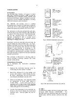
To reset the total display from the safe area a
Zener barrier or intrinsically safe relay is required
to transfer the contact closure into the hazardous
area. Almost any intrinsically safe relay with
certification permitting the contacts to be
connected to equipment in the hazardous area
may be used. Alternatively, a positive polarity
Zener barrier with intrinsic safety parameters equal
to or less than the input safety parameters of the
reset terminals may be used as shown in Fig 3A.
The total resistance of the barrier, switch and
interconnecting wiring must be less than 1kΩ.
Note:
The negative reset terminal RS2 is internally
connected to the negative 4/20mA input
terminal 3.
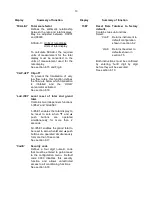
3.5 Certification label information
The certification information label is fitted in a
recess on the top outer surface of the instrument
enclosure. It shows the ATEX certification
information and BEKA associates' name and
location. Non European certification information
may also be shown. The instrument serial number
and date of manufacturer are recorded on a
separate label inside the terminal compartment.
BA354E certification label
6


