


9
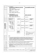
Suppression / elevation links
Position
see Fig 7
Display with 4mA
input adjustable
Between
Elevation
Suppression
0 and 1000
0 and -1000
Zero link
Position
see Fig 7
Display with 4mA
Input adjustable
Between
0 to 500
500 to 1000
0 and 500
500 and 1000
6.2 Span adjustment
Span is defined as the difference between the
number displayed with 4.000mA input and the
number displayed with 20.000mA input. It is
adustable between 0 and 1999 in four ranges. Fig
7 shows the position of the span links and the span
potentiometer.
Span links
Position
see Fig 7
Difference in
Display with
4 & 20mA input
adjustable between
000 to 500
500 to 1000
1000 to 1500
1500 to 1999
000 and 500
500 and 1000
1000 and 1500
1500 and 1999
6.3 Decimal point
A decimal point may be displayed between any of
the four digits. The position or absence of this
dummy decimal point is determined by the
position of the decimal point link shown in Fig 7.
When calculating the required span and zero
setting, the decimal point should be ignored.
6.4 Reverse action
Normally the instrument display increases as the
input current increases, but this can be reversed.
Please contact BEKA associates for details.
6.5 Calibration example
A BA307C is required to display:
25.0 with a 4.000mA input
115.0 with a 20.000mA input
i.e.
A zero of positive 250
Ignoring
A span of 900
decimal point
A decimal point in position 00.0
The following adjustments are required:
Step 1
The BA307C is required to display a
positive zero therefore the suppression
/ elevation links should be put in the
elevation position.
Step 2
The required zero is 250, therefore the
zero link should be put in the 0 to 500
position.
Step 3
The required span is 900, therefore the
span links should be placed in the 500
to 1000 position.
Step 4
The decimal point is required before the
least significant digit, therefore the
decimal point link should be placed in
the 00.0 position.
Step 5
With 4.000mA input adjust the zero
potentiometer until the indicator
displays 25.0
Step 6
With 20.000mA input adjust the span
potentiometer until the indicator
displays 115.0
Step
7
Repeat steps 5 and 6 until both
calibration points are correct. The span
and zero controls are almost
independent so it should only be
necessary to repeat each adjustment
twice.
6.6 Over and under-range
If the indicator display range is exceeded, the three
least significant digits will be blanked. Under-
range is indicated by -1 and over-range by 1. If
the display range is not exceeded, both indicators
will produce accurate readings outside the 4/20mA
current range. Although not guaranteed, most
BA307C and BA308C indicators will operate
between 3 and 25mA.
]


