7
Fig 4B BA308C dimensions
5.2 Installation Procedure
a.
Insert the indicator into the panel aperture
from the front of the panel.
b.
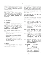
Fix two panel mounting clips to opposite
sides of the instrument enclosure and tighten
until the indicator is secure as shown in Fig
5. Four clips are required to achieve an
IP65 seal between a BA308C enclosure and
the instrument panel.
c.
Connect the panel wiring to the rear terminal
block(s) as shown in Figs 4A and 4B. To
simplify installation, the terminals are
removable so that the panel wiring can be
completed before the instrument is installed.
Fig 5 Fitting panel mounting clips
5.3 EMC
Both instruments comply with the requirements of
the European EMC Directive 2004/108/EEC. For
specified immunity all 4/20mA wiring should be in
screened twisted pairs with the screen earthed
within the safe area. The indicator enclosure may
be earthed locally by putting a tag under one of the
rear panel corner fixing screws. EMC
performance is shown in the instrument
specification, and copies of the test report are
available from BEKA associates.

