5
4.
SYSTEM DESIGN FOR HAZARDOUS
AREAS
4.1 Transmitter loops
The BA307C and BA308C may be connected in
series with almost any intrinsically safe 4/20mA
current loop and calibrated to display the
measured variable or control signal in engineering
units. There are two basic design requirements:
1.
The intrinsic safety output parameters of the
4/20mA loop, which are defined by the Zener
barrier or galvanic isolator, must be equal to
or less than:
Uo = 30V dc
Io
= 200mA
Po = 0.85W
2.
The loop must be able to tolerate the
additional 1.1V required to operate the
indicator.
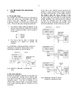
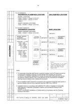
Fig 2 illustrates a typical application in which an
indicator is connected in series with a 2-wire
transmitter protected by a Zener barrier.
Fig 2 BA307C or BA308C in a transmitter
loop
4.2 Remote indication
BA307C and BA308C indicators may be driven via
an intrinsically safe interface from a 4/20mA safe
area signal to provide a remote indication within a
hazardous area. The type of interface is not
critical, either a Zener barrier or a galvanic isolator
may be used, providing that Uo, Io and Po are not
exceeded.
If one side of the 4/20mA current loop may be
earthed, a single channel Zener barrier provides
the lowest cost protection. If the 4/20mA signal is
not isolated, then two Zener barriers, a two
channel Zener barrier or a galvanic isolator should
be used. Again it is necessary to ensure that the
voltage capability of the 4/20mA signal is sufficient
to drive the indicator plus the voltage drop
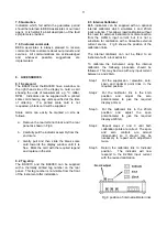
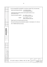
introduced by the intrinsically safe interface. Fig 3
shows the alternative circuits which may be used.
Fig 3 Alternative circuits for remote
indication in hazardous area

