8
INTELLIGATE XR2000
1.2.1 Front panel
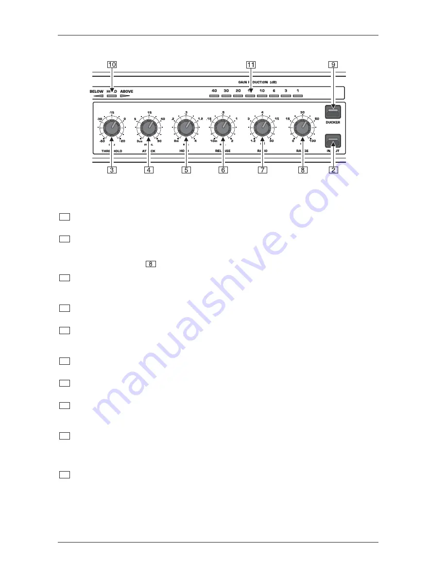
Fig. 1.2: Control elements of the Expander section
2
The IN/OUT switch engages the corresponding channel. This switch is used to make direct A/B
comparisons between source material and the processor’s effected signal.
3
The THRESHOLD control adjusts the threshold level for the expander/gate section in the range of -50 to
+20 dBu. Signals below this level cause attenuation. As the key signal passes through threshold, the
release and hold functions are triggered, dropping the gain of the Expander/Gate to the value determined
by the RANGE control
. In Ducker mode these funtions are reversed.
4
The ATTACK control adjusts the time taken to reach unity gain after the key signal exceeds threshold.
When in the Ducker mode, this control adjusts the rate of attenuation after the key signal exceeds the
threshold. The control range lies between 3
µ
s and 90 milliseconds.
5
The HOLD control adjusts the period of delay before the onset of the release function, after the signal
falls below the threshold. The control range lies between 8 milliseconds and 4 seconds.
6
The RELEASE control adjusts the time taken for the gain to be reduced to a value set by the RANGE
control. When in the Ducker mode, this control adjusts the rate of recovery to unity gain after the hold
cycle is complete. The control range lies between 10 milliseconds and 2 seconds.
7
Use the RATIO control to adjust the ratio of the downward expander. It defines the relationship between
the input and the output level which fall below the threshold. The control range lies between1.2:1 to 30:1.
8
The RANGE control determines the maximum amount of attenuation. The control range lies between
0 dB up to 100 dB.
9
The DUCKER switch changes the operation from the Expander to the Ducker and the control signal is
inverted. When the key signal exceeds the threshold, the gain of the Ducker is now decreased and the
output is returned to unity gain when the key signal falls below the threshold.
10
The arrangement of the LEDs in this application is called “traffic lights” and indicates the operating
status of the unit. The BELOW LED (red) indicates that the key signal is below threshold. The HOLD
LED (yellow) indicates that the hold circuit is active. The ABOVE LED (green) indicates that the key
signal is above threshold.
11
The 8-stage GAIN REDUCTION meter informs you of the actual gain reduction and displays this in a
range of 0 to 40 dB.
1. INTRODUCTION


