


Commissioning
EL922x
131
Version: 1.0
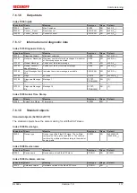
7.6.3
EL9227-xxxx
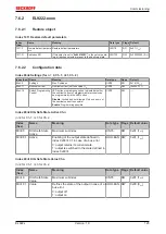
7.6.3.1
Restore object
Index 1011 Restore default parameters
Index
(hex)
Name
Meaning
Data type
Flags Default
1011:0
Restore default parame-
ters
Restore default parameters
UINT8
RO
0x01 (1
dec
)
1011:01
SubIndex 001
If this object is set to "
0x64616F6C"
in the set value dia-
log, all backup objects are reset to their delivery state.
UINT32
RW
0x00000000 (0
dec
)
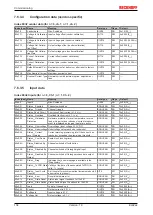
7.6.3.2
Configuration data
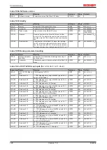
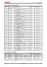
Index 80n0 Settings (for n = 0, Ch.1; n = 1, Ch. 2)
Index (hex) Name
Meaning
Data type
Flags
Default
80n0:0
Settings
Max. Subindex
UINT8
RO
0x1A (26
dec
)
80n0:11
Nominal current
Nominal current (set fuse value), I
N
UINT8
RW
(0x80nF:17)
80n0:12
Characteristic
Characteristic curve: Indicates the time after which
the system is switched off at which current level.
UINT8
RW
0x01 (1
dec
)
80n0:13
Current-Level Warn-
ing
Prewarning: Indicates the current value from which a
prewarning is issued.
UINT16
RW
0x005A (90
dec
)
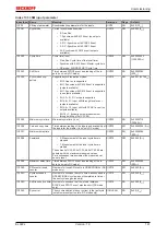
80n0:14
Fuse Init State
Initialization state: Describes the state of the outputs
which they should have when the voltage is applied
again after a voltage interruption.
Off, On
or return to
the
last state
when the voltage was still applied
.
UINT8
RW
0x02 (2
dec
)
80n0:15
Input Functions (DI &
Switch)
Input functions (digital input & LED button): De-
scribes the function of the digital input and the LED
button which should be executed if required. It de-
scribes the behavior, so to speak.
Reset
only,
power
on/off
only,
reset and power on/off
or
disabled
.
UINT8
RW
0x02 (2
dec
)
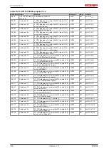
80n0:16
Overvoltage Behav-
iour
Overvoltage behavior: Describes how the outputs
should respond when an overvoltage (>32 V DC,
hysteresis 2 V) is present at the input.
Tripping
and
do not switch on again automatically when the over-
voltage has been resolved, or
tripping with auto re-
set
and automatic switching on again when the over-
voltage has been resolved.
UINT8
RW
0x01 (1
dec
)
80n0:17
Undervoltage level
Undervoltage threshold: This is the value from which
an undervoltage (adjustable from 17 to 24 V DC, hys-
teresis 1 V) is displayed.
UINT8
RW
0xAA (170
dec
)
80n0:18
Reverse Current Filter Reverse feed filter: Describes when the system is
switched off if the voltage at the output is 1 V higher
than at the input.
Fast
: Switch-off at reverse feed >10 ms
Standard
: Switch-off at reverse feed >100 ms
Slow
: Switch-off at reverse feed >1,000 ms
UINT8
RW
0x01 (1
dec
)
80n0:19
Switch Programming
Control
LED button programming option: Indicated whether
the nominal current of programmable terminals can
be programmed via the LED button.
Disable
: Locked and not allowed. Only one query of
the nominal current is possible!
Enable
: Programming possible
UINT8
RW
---
80n0:1A
Switch On Channel
Delay
Channel switch-on delay: Describes the behavior of
the switch-on delay from channel 2 to 1.
Off
: No delay from channel 2 to 1.
On:
Switch-on delay between channels 1 and 2
(channel 2 typically 50 ms after channel 1).
UINT16
RW
0x0000 (1
dec
)


