Electrical installation
Version: 4.3
───
101
AM8000 and AM8500
9.1.5
Terminal box
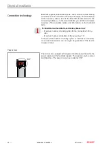
Avoid soiling and damage
When dismantling the cover and connecting the terminal box and
cables, make sure that no foreign objects or dirt particles enter the
terminal box, the clamping ring or the M40 thread on the terminal
box.
Failure to do so may adversely affect the function of the connec-
tions.
Assembly of the power cable and feedback cable
When assembling the cables, note that the size of the blind plug
thread in the terminal box is M40.
1+2
3+4
5
6
1+2
3+4
5
6
1+2
3+4
5
6
1+2
3+4
5
6
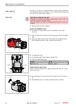
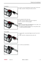
► Make sure that the rubber seal [6] in the cover [5] is not lost or
damaged
► Loosen and remove screws [1] to [4]
► Remove cover [5]
7
8
9
7
8
9
7
8
9
► Loosen clamping ring [8]
► Insert motor cable [7] through clamping ring [8] into terminal box
[9]
Motor cable
Order details
10 mm² for motors with terminal
box
ZK4506-8027-xxxx
16 mm² for motors with terminal
box
ZK4506-8018-xxxx
8
8
8
► Fasten clamping ring [8] to the terminal box
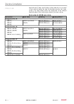
► Connect the cable ends to the terminal according to the assign-
ment diagram
Important
The assignment diagram of the terminal box can be found below:
Technical data AM807x.
► Make sure that the seal is correctly placed on the terminal box
► Re-install the cover [5]
Summary of Contents for AM8000 Series
Page 1: ...Operation Instructions EN AM8000 and AM8500 Synchronous Servomotors 8 27 2020 Version 4 3 ...
Page 2: ......
Page 122: ......


