20
Operating Instructions
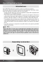
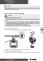
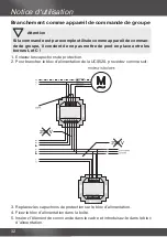
3. Put the protective caps back on the power supply unit.
4. Fix the power supply unit in the box.
5. Put the operating device in the frame and plug it into the power supply unit.
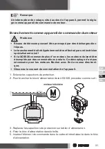
1. Remove the protective caps.
2. Connect the power supply unit to the UCS520 as follows:
Connection as a group controller
Attention
If the control is used as a group control device, for example, no bridge
can be inserted between the L and C terminals!
Summary of Contents for Centronic UnitControl UCS520
Page 9: ...FR GB DE NL 9 Anzeigen und Tastenerklärung ...
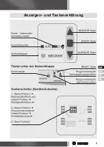
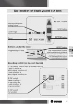
Page 21: ...FR GB DE NL 21 Explanation of displays and buttons ...
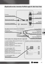
Page 33: ...FR GB DE NL 33 Explication des textes d affichage et des touches ...
Page 45: ...FR GB DE NL 45 Verklaring van displays en toetsen ...
Page 52: ...4031 630 011 0a 08 05 DE GB FR NL 309156 01 Becker Antriebe GmbH 35764 Sinn Germany ...

