BEA 10WIZARDSMR User Manual Download Page 3

75.0127 V3 Jul. 2003 [Rev. 8/13/2004]


Page 3 of 17 

ELECTRICAL 

INSTALLATION


ELECTRICAL 

INSTALLATION – 

WIRING


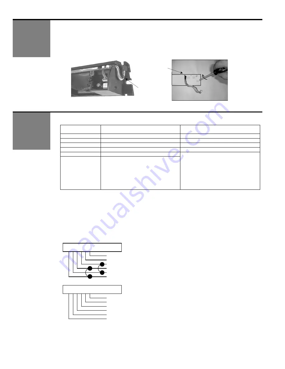
1.        With  Wizard  in  place,  locate  the  enclosed  cable  and  feed  the  stripped  end  through  the  wire 

passage hole in header from the Wizard side as shown in Picture (F). Leave enough slack to 

allow connection to the Wizard and proper routing of wire around the plastic posts (E). Please 

observe proper routing of the cable as shown – this is to divert rainwater from the Wizard if it 

should run down the cable, and also provides for proper routing to allow easy cover installation 

on the Wizard. 


Perform the following for wiring the Wizard to an automatic door control: 


Wizard Wire 

Color 

Connect To: 

Microprocessed Controls 

Connect To: 

Old Style Controls 

Red 

12 to 24  VAC / VDC: -5%  to +10% 

12 to 24  VAC / VDC: -5%  to +10% 

Black 

12 to 24  VAC / VDC: -5%  to +10% 

12 to 24  VAC / VDC: -5%  to +10% 

White 

Common at Door Control 

Common at Door Control 

Green 

Activation Input at Door Control 

Activation Input at Door Control 

Brown 

Common at Door Control 

Blue 

Safety Input at Door control 

Brown & Blue wires are not used for SN 

52000 and greater – Do NOT Connect 

Them To Anything:  

All output is through the white and green 

wires. 

The Wizard MUST be programmed 

to a Relay Configuration value of 5 or 6. 

See Page 8. 

Wizards below SN 52000 will 

still require a 10IFBWIZARD. 


Other Wiring Notes: 


1.  When connecting to a microprocessed control box, the Motion output and presence output wires 

may be connected to separate inputs or may also be to a mutual input, as some controls may 

only have an activation input, while others may have an activation input, as well as a safety (or 

presence) input. For example: 


FOR CONTROLS WITH ONLY AN ACTIVATION INPUT: 

Two options exist for this configuration. First the White and Green may be connected to Brown and 

Blue (respectively), OR the Relay Configuration may be set to a value of 5 or 6, in which case ONLY 

the White and Green wires are used. 


OR 


2.  If separate outputs are available at the control box, White and Green may go to common and activation, 

while Brown and Blue will go to the safety (or presence) input. Always respect polarity with Brown and 

Blue. 


Plastic 

post to 

wrap wires 

around 


WIZARD 

MOUNTING 

TEMPLATE 

Wire fed 

through 

towards 

control 

Plastic post 

to wrap wires 

around 

WIZARD 

Red - 12 to 24  VAC / VDC: -5%  to +10%  

Black - 12 to 24  VAC / VDC: -5%  to +10% 

White – Common at Door Control 

Green – Activation at Door Control 

Brown  

Blue 

WIZARD 

Red - 12 to 24  VAC / VDC: -5%  to +10%  

Black - 12 to 24  VAC / VDC: -5%  to +10% 

White – Common at Door Control 

Green – Activation at Door Control 

Brown – Not Used 

Blue – Not Used 

For SN 52000 and greater, 

program the Wizard to Relay 

Configuration Value 5 or 6. If 

set to 5, contacts close upon 

detection. If set to 6, 

contacts open upon 

detection. 

OBSOLETE

Summary of Contents for 10WIZARDSMR

Page 1: ...0 g Housing material ABS LURAN S Color of Housing Anthracite gray standard aluminum or white finish Cable length 8 of six conductor cable MOTION SENSOR PRESENCE SENSOR Technology Microwave and microprocessor Transmitter frequency 24 125 GHz Transmitter radiated power 20 dBm EIRP Transmitter power density 5 mW cm Focused active infrared and Self monitored microprocessor Spot diameter standard 4 max...

Page 2: ...the unit as shown in picture A After the Wizard is attached to the header the cover may be removed by inserting small screwdriver behind the Wizard and gently prying cover off as shown in picture B 2 Attach mounting template to the center of header as shown C template should be 0 2 above bottom edge of header Drill the hole marked for wire passage and drill pilot holes for screw mounting D NOTE Fl...

Page 3: ...elow SN 52000 will still require a 10IFBWIZARD Other Wiring Notes 1 When connecting to a microprocessed control box the Motion output and presence output wires may be connected to separate inputs or may also be to a mutual input as some controls may only have an activation input while others may have an activation input as well as a safety or presence input For example FOR CONTROLS WITH ONLY AN AC...

Page 4: ...attern being drawn back towards the door where as the 45ºwill place the pattern farther away Be certain to walk test detection field and insure compliance with current applicable ANSI standards 1 Insert the desired microwave planar antenna for a narrow or wide field of detection Refer to the diagram below for approximation of field size for each pattern 7 0 height 13 W X 6 6 D 6 6 W X 8 2 D The op...

Page 5: ...l bring the pattern nearer or farther from the face of the door by adjusting the tilt angle from 4 to 4 At the standard mounting height one complete clockwise turn of the adjustment screw will move the pattern approximately 3 inches closer to the door The precise location of the infrared beam may be found by using the BEA Spot finder PN 10SPOT after the Wizard has been powered up Open the battery ...

Page 6: ...ing and the sensor will no longer be in a program mode Locked with existing code 0 9 0 9 0 9 0 9 Locked with new code that is entered KEY USER S ACTIONS DEFAULT LED STATUS Press the function key that you desire to inquire about followed by pressing the INQUIRY key After pressing INQUIRY count the number of green LED flashes this corresponds to the setting EXAMPLE After pressing a function button t...

Page 7: ... red LED flashes quickly After pressing a number button the red LED flashes slowly IMMUNITY motion Immunity reduces the influence of unwanted disturbances within the field of motion detection without reducing the pattern 1 Extreme sensitivity 2 Normal Sensitivity 3 Reduced sensitivity 2 After pressing the IMMUNITY key the red LED flashes quickly After pressing a number button the red LED flashes s...

Page 8: ...econds 0 0 30 second learn time 4 Lock The Sensor when complete 5 After the above changes have been made the Wizard will go into the Snow Mode after it goes through 2 auto learn cycles without having a minimum of 6 operating cycles of the door between these 2 auto learn cycles 6 While in Snow Mode the auto learn time will change from 30 seconds to 10 seconds This mode will automatically expire upo...

Page 9: ...o standard mode Press the right button again until the LED light stops flashing and then release CUSTOMIZING MODE The red LED light indicates the number for the parameter being altered 1 flash parameter 1 The green LED light indicates the value for the parameter being altered 1 flash means value 1 The right button enables selection of the parameter number being altered 1 for each press The left bu...

Page 10: ... the status of the set up Observe the LED while standing outside of the detection zones NO LED Successful set up RED LED ON Presence being detected Wizard is seeing an object RED LED Flashing for 10 seconds Infrared curtains are too close to door Adjust curtains using the Spotfinder GREEN LED MOMENTARILY ON MOTION DETECTION Wizard sees movement ORANGE LED ON Wizard is executing a Self Monitoring t...

Page 11: ... door is in ON or AUTOMATIC position If it is in correct position check switch with multi meter for proper operation 2 Walk in and out of Wizard detection area if red LED does not illuminate check a Power supply for Wizard 12 to 24 VAC VDC 5 to 10 b Check SMR setting on each Wizard The SMR should be disabled unless system is being used with BEA s Door Control Unit DCU c Check Relay Configuration f...

Page 12: ...1 5 volt Wizard will not unlock when access code is entered 1 Improper code being entered 1 Reset code to the default value of 0000 by performing one of the following a Press the 2 buttons on the Wizard simultaneously until the red green led begin flashing This will return ALL settings to their default value b Cut and restore power supply No code is required to unlock during the first minute after...

Page 13: ...TB 3 of the interface PH 412 249 4100 FAX 412 249 4101 B E A Inc 100 Enterprise Drive Pittsburgh PA 15275 REV 1 OF 1 NONE SIZE CAGE CODE DWG NO FILE OF GDM 20 MAR 2002 GDM A STANLEY DURAGLIDE WITH WIZARD SYSTEM TITLE STANLEY DURAGLIDE WITH WIZARD SYSTEM C NOTES 1 WIZARDS WILL OPERATE WITH THE 12 VDC ON PINS 1 2 5 6 2 ONE WAY FUNCTION IS APPLICABLE IF CLOSED DOOR MONITORING SWITCH IS INSTALLED BROW...

Page 14: ...E BLACK RED WHITE BROWN BLUE BLACK RED GREEN Reset 0 VDC Part open Exit Off 0 VDC Stop Impulse Pres Impulse 1 C Switch 0 v Pres Impulse 2 18 VDC 0 VDC Outer Impulse Inner Impulse 18 VDC PS 6 Optional connect to reset TB1 R if required LOCKING DEVICE 24 VAC GREEN WHITE BESAM CUJ 9 AMD II SLIDING DOOR WITH WIZARD SYSTEM 608 NOTE 1 DO NOT CONNECT TO C SWITCH COMMON 2 OBSERVE POLARITY WITH BROWN CONNE...

Page 15: ...IMPULSE 24 VDC MONITORED SAFETY ONLY PHOTOCELL BESAM UNISLIDE SLIDING DOOR WITH WIZARD SYSTEM SIZE SHEET SCALE A PH 412 249 4100 FAX 412 249 4101 B E A Inc 100 Enterprise Drive Pittsburgh PA 15275 DATE www beasensors com CAGE CODE DWG NO FILE OF DRAWN BY REV 1 OF 1 NTS Tech Support 80 0163 GDM B 11 Mar 2003 TITLE BESAM UNISLIDE SLIDING DOOR WITH WIZARD SYSTEM NOTE 1 DO NOT CONNECT BROWN WIRES TO C...

Page 16: ...WITCH PINS 5 6 7 LOOK SEE COM LINE PIN 8 LOOK SEE OUTPUT PINS 17 18 96010 900 QUANTUM SLIDE CONTROL BOX ACCESSORIES 24 VDC PIN 1 PIN 2 ACCESSORIES 24 VAC PINS 3 4 4 PIN 5 PIN EARTH GROUND NEUTRAL MAIN 3 PIN RA WH 1 RA BL 2 EA WH 3 EA BL 4 5 NC 4 NO 3 COM 2 12 24 vac dc 1 12 24 vac dc RB WH 1 RB BL 2 EB WH 3 EB BL 4 1 2 3 4 RECEIVER A EMITTER A RECEIVER B EMITTER B WH WHITE BL BLACK MICROCELL ONE G...

Page 17: ... SW COMMON CLS MON SW COMMON PARTIAL OPEN 2WAY 1 WAY NIGHT SW COMMON DAY NITE SW 24VDC 24VDC B E A Inc DATE REV DRAWN BY SHEET 1 OF 1 SCALE NONE SIZE CAGE CODE DWG NO FILE OF ENG G 05 JAN 04 JED A 01 TITLE HORTON C2150 CONTROL WITH WIZARD SYSTEM HORTON C2150 CONTROL WITH WIZARD SYSTEM C2150 CONTROL NOTE 1 WIZARDS WILL OPERATE WITH THE 24 VAC ON THE C3938 POWER SUPPLY CN3 100 Enterprise Drive Pitts...

Reviews: