P R O D U C T I N F O R M A T I O N
Rear Panel Detail
6
Introduction
Edition 1.07
CXPS Manual
. . . . . . . . . . . . . . . . . . . . . . . . . . . . . . . . . . . . . . . . . . . . . . . . . . . .
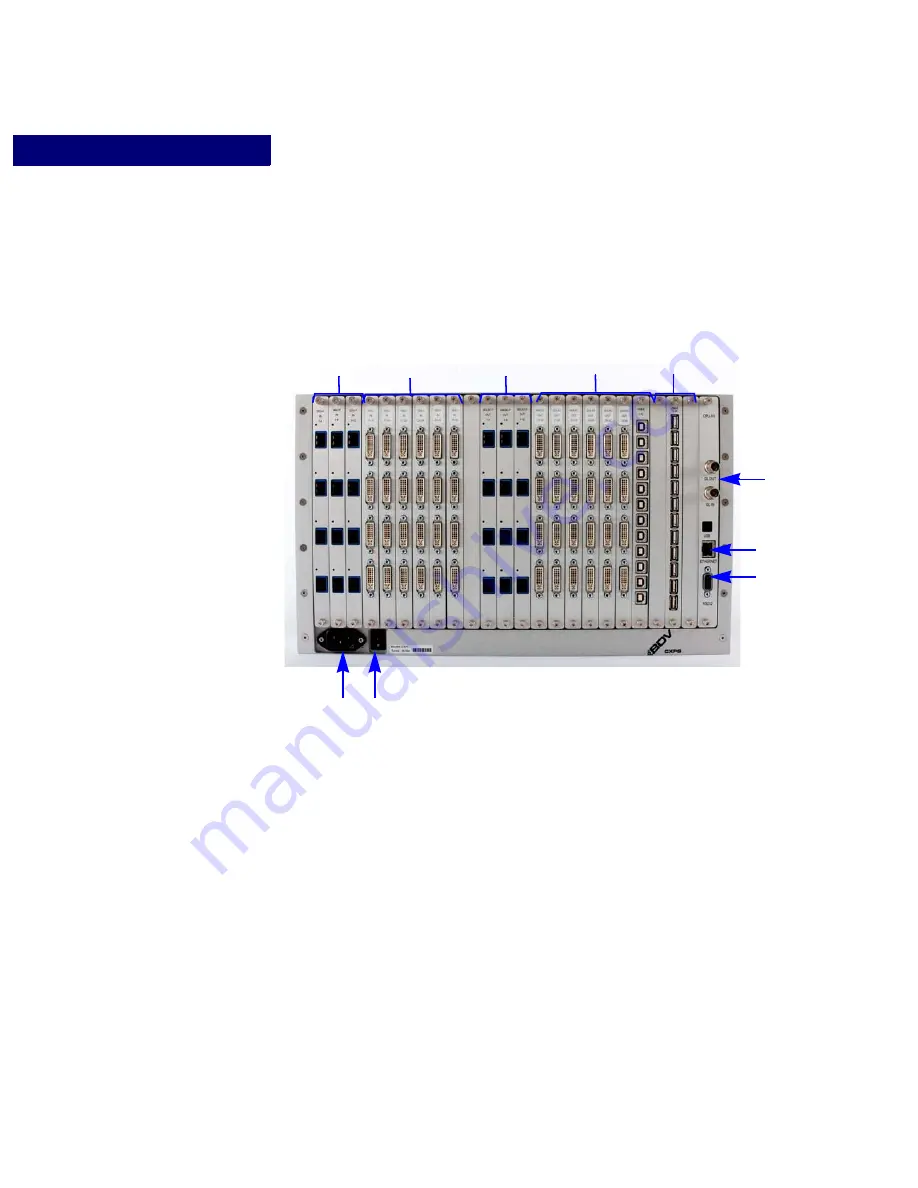
R E A R P A N E L D E T A I L
Figure 3
details a fully-equipped CXPS. Your device may be configured with fewer
connections.
1
- A C P O W E R I N
AC input power connection (120/240 VAC).
2
- P O W E R S W I T C H O N / O F F
The power switch is used to turn the unit on or off. The system status light on the front panel
indicates when the unit is powered on.
3
- D V I - I I N P U T C O N N E C T I O N S
The DVI-I input connectors are used to connect a video source to the CXPS. If the input
source is a DVI source, it can be connected directly to the device. If the input source is an
analog or SDI source, the signal must first be converted to DVI using a Black Diamond
Video DVI converter before connecting it to the CXPS.
FIGURE 3.
CXPS Rear Panel Diagram
(3)
(4)
(8)
(7)
(6)
(5)
(1)
(2)
(9)
(10)
Summary of Contents for CXPS
Page 1: ...CXPS Manual Edition 1 07 August 10 2011 BDV BLACK DIAMOND VIDEO ...
Page 6: ...vi Contents Edition 1 07 CXPSManual ...
Page 82: ...VI D E O WI N D O W I N G Cropping 76 Operation Edition 1 07 CXPSManual ...
Page 102: ...WAL L P RO C E S S I N G Switching Input Sources 96 Operation Edition 1 07 CXPSManual ...
Page 124: ...R S 23 2 A N D 1 0 1 0 0 T P RO T O C O L RS 232 Pinout 118 Reference Edition 1 07 CXPSManual ...
Page 128: ...U P G R A DI N G F I R M W A RE 122 Reference Edition 1 07 CXPSManual ...


