background image


BAYKAL


EDITION NO          :    

HGL 

SECTION   : 


DATE OF ISSUE   : 

November 2009 

PAGE         : 

81


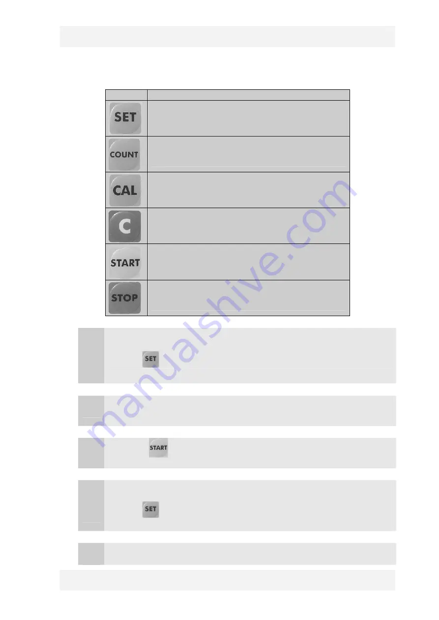
Figure 6.5.6.36


Key 

Description 


Set key

 display shows 


Quantity counter set key


Calibration Key


Clear key


Start and Enter key


Stop and Cancel key


   1. 


How to position the back-gauge 


Press set           key. The display will show 00000.


   2. 


Write desired position to the display by using numerical keys. 


   3. 


Press start            key. The back-gauge will move the desired position. 


   1. 


How to enter quantity 


Press set           key. The display will show 00000. 


   2. 


Write desired position to the display by using numerical keys. 

Summary of Contents for HGL C Series

Page 1: ...SSUE November 2009 PAGE 1 USER MANUAL HYDRAULIC SHEAR MODEL HGL Machine Types HGL CXXXXX Xxx HGL SXX0XX Xxx No part of this User s Manual may be reproduced or transmitted by any without Prior permissi...

Page 2: ...X X X X X XXX C CE S STAND 1 220 2 230 3 240 4 400 5 415 6 440 7 480 8 600 9 220 400 1 PRG 911 2 ELGO 9521 3 S3 0 NO SAFETY 1 LE 20 SICK 2 PHOTOCELL 1 MANUAL 2 MOTORIZED 1 BOSH 2 REXTROTH 3 BOSH REXTR...

Page 3: ...BAYKAL EDITION NO HGL SECTION DATE OF ISSUE November 2009 PAGE 3 ATTENTION PUMP ROTATION MUST BE IN ARROW DIRECTION OTHERWISE THE PUMP WILL BE DAMAGED...

Page 4: ...ER ELECTRIC SHOCK GROUND LUBRICATION PUMP ROTATION POINT DESIGNATION PLATE Manufacturer BAYKAL Mak San Tic A Bursa T RK YE Machine Hydraulic Shear Type HGL Model Serial No Cutting Capacity ton Cutting...

Page 5: ...TRANSPORTATION 5 UNPACKING INSTALLATION 6 OPERATING AND MAINTENANCE INSTRUCTIONS 6 1 Technical data 6 2 Description of shear applications 6 3 Prohibited uses of the shear 6 4 Incorrect uses of the she...

Page 6: ...ON DATE OF ISSUE November 2009 PAGE 6 1 GENERAL MACHINE INFORMATION 1 1 Registered trademark BAYKAL 1 2 Machine type HGL 1 3 Serial number 1 4 Year of manufacture 1 5 Address of manufacturer 1 6 Addre...

Page 7: ...stop buttons engaging type are available on the electrical cabinet on the foot switch control unit and on the right hand side of the upper frame of the machine all of which are easily accessible Figu...

Page 8: ...pply failure during operation the beam will stop at a standstill When power supply is recovered it is NOT possible to start the machine without resetting Figure 2 2 The rear of the shear is covered by...

Page 9: ...YKAL EDITION NO HGL SECTION DATE OF ISSUE November 2009 PAGE 9 The plate a and grid b are used to protect the operator from accidental contact while the cutting beam is moving upward and downward b b...

Page 10: ...machine is to be installed must be accounted for 4 The machine must be operated only by authorized and trained personnel Operation by unauthorized and untrained Personnel in a way that does not compl...

Page 11: ...ons and immediately shut down the machine when a danger is noticed Shut off the machine completely before any repair work is carried out DO NOT access into the backgauge area while the machine is work...

Page 12: ...o special personal safety equipment is necessary It is however recommended to use working gloves when handling the work pieces 9 General maintenance of the shear can be carried out by universal tools...

Page 13: ...ERALL DRAWING Mak Tip A A1 B B1 B2 B3 C HGL 2600X6 2760 3190 1260 1200 1740 2940 1560 HGL 3100X6 3260 3740 1320 1200 1800 3000 1576 HGL 3100X8 3305 3735 1450 1200 1930 3130 1650 HGL 3700X6 3965 4395 1...

Page 14: ...that the machine is not subjected to impact during loading or unloading The crane to lift the machine must be controlled by a single operator The following points should be taken into account The lift...

Page 15: ...BAYKAL EDITION NO HGL SECTION DATE OF ISSUE November 2009 PAGE 15 Figure 4 1...

Page 16: ...or to visualize the work area without obstruction Therefore the hazardous situations regarding the operator other persons or materials due to incorrect installation will be reduced To facilitate colle...

Page 17: ...BAYKAL EDITION NO HGL SECTION DATE OF ISSUE November 2009 PAGE 17 INSTALLATION DIAGRAM...

Page 18: ...9 Number of holddowns pcs 10 Strokes per minute cuts min 11 Pump flow rate cm rev 12 Oil tank volume lt 13 Back gauge range mm 14 Main motor 3 phase 220V 60Hz kW 15 Back gauge 3 phase 220V 60Hz kW 6 1...

Page 19: ...7 Warning Out of warranty 6 1 4 List of bearings and special parts No Parta Name Part no description Qty Location on machine 1 Self aligning roller bearing GE 60 ES 2 Top Beam 2 Bearing 16006 4 Blade...

Page 20: ...d retracts by a spring system A set of top and bottom blades which are made of specially hardened steel material execute the shearing process The gap between blades varies according to workpiece thick...

Page 21: ...rking area between top and bottom blades When any of the protective devices or guarding of the machine are NOT mounted or NOT functioning For shearing operations involving non flat metals at origin e...

Page 22: ...surface b Blade gap is greater than necessary Blades get blunted and may break The sheared material may get jammed between blades The sheared material edge is burred 2 Incorrect use Cutting over capac...

Page 23: ...BAYKAL EDITION NO HGL SECTION DATE OF ISSUE November 2009 PAGE 23 Non recommended use Cutting high silica and high carbon material Consequence Blades get blunted...

Page 24: ...er Check that the blades are rigidly fixed in their places Make sure that the cables are not damaged Check the components and terminal ends inside the electrical cabinet against any loosening Make sur...

Page 25: ...y supply cable with correct diameter EARTHING connection is strictly necessary Voltage and power requirements are labeled on the machine First class components are used in the electrical cabinet all e...

Page 26: ...ATE OF ISSUE November 2009 PAGE 26 B Light barrier connections and main switch a b c d Figure 6 5 2 2 Figure Label Electrical Diagram Description a Light guard connector b 2S5 Reset button c Light gua...

Page 27: ...ck gauge connections and the top bottom limit switches a c b e Figure 6 5 2 3 Figure Label Electrical Diagram Description a 1M5 Back gauge motor connection b 3S8 Back gauge limit switch c 3S7 Back gau...

Page 28: ...adjustment motor is on the right side of the machine if the machine has Motorized blade gap adjustment system Figure 6 5 2 4 Figure 6 5 2 5 Figure Label Electrical Diagram Description a 1M7 Blade gap...

Page 29: ...witches is present on the rear of the electrical cabinet on the left side of the machine if the machine has Motorized blade gap adjustment system Figure 6 5 2 6 Figure Label Electrical Diagram Descrip...

Page 30: ...N DATE OF ISSUE November 2009 PAGE 30 D Hydraulic Valve connections Figure 6 5 2 7 No Name Description 1 Directional Valve It controls downward movement of the beam 2 Directional Valve It controls upw...

Page 31: ...3 1 1 Control Unit with PRG 911 digital controller Hourcounter Back gauge backward button Inside illumination switch Beam down button Beam up button Pump stop button Reset lamp Reset button Beam up an...

Page 32: ...ring the beam 3S4 Pump stop button When pressing the main pump stops 3S5 Pump start button When pressing the main pump starts up 2S2 Front Emergency stop button In case of emergency when pressing all...

Page 33: ...Sheet Holder Digital Controller Back gauge forward button Stroke adjustment timer Cutting Control Switch Pump start button Control on Front Emergency stop button Pneumatic support switch Hourcounter B...

Page 34: ...hen pressing the main pump stops 3S5 Pump start button When pressing the main pump starts up 2S2 Front Emergency stop button In case of emergency when pressing all machine functions and controls will...

Page 35: ...ontroller Digital Controller P400 Back gauge backward button Inside illumination switch Beam down button Beam up button Pump stop button Reset lamp Reset button Beam up and lamp Digital Controller Bac...

Page 36: ...It is used for lowering the beam 3S4 Pump stop button When pressing the main pump stops 3S5 Pump start button When pressing the main pump starts up 2S2 Front Emergency stop button In case of emergenc...

Page 37: ...ic Sheet Holder CE Back gauge backward button Beam down button Beam up button Pump start button Pump stop button Reset lamp Reset button Beam up and lamp Hourcounter Digital Controller Back gauge forw...

Page 38: ...g the beam 4S5 Beam down button It is used for lowering the beam 3S4 Pump stop button When pressing the main pump stops 3S5 Pump start button When pressing the main pump starts up 2S2 Front Emergency...

Page 39: ...l controller Hourcounter Back gauge forward button Stroke adjustment timer Cutting Control Switch Pump start button Control on Front Emergency stop button Digital controller Back gauge backward button...

Page 40: ...ring the beam 3S4 Pump stop button When pressing the main pump stops 3S5 Pump start button When pressing the main pump starts up 2S2 Front Emergency stop button In case of emergency when pressing all...

Page 41: ...trollers Digital Controller P9521 Back gauge forward button Stroke adjustment timer Cutting Control Switch Pump start button Control on Front Emergency stop button Digital controller P400 Back gauge b...

Page 42: ...ton It is used for lowering the beam 3S4 Pump stop button When pressing the main pump stops 3S5 Pump start button When pressing the main pump starts up 2S2 Front Emergency stop button In case of emerg...

Page 43: ...neumatic Sheet Holder Hourcounter Back gauge forward button Stroke adjustment timer Cutting Control Switch Pump start button Control on Front Emergency stop button Pneumatic support switch Digital con...

Page 44: ...pressing the main pump stops 3S5 Pump start button When pressing the main pump starts up 2S2 Front Emergency stop button In case of emergency when pressing all machine functions and controls will be i...

Page 45: ...et Holder Digital Controller P9521 Back gauge forward button Stroke adjustment timer Cutting Control Switch Pump start button Control on Front Emergency stop button Pneumatic support switch Digital co...

Page 46: ...Pump stop button When pressing the main pump stops 3S5 Pump start button When pressing the main pump starts up 2S2 Front Emergency stop button In case of emergency when pressing all machine functions...

Page 47: ...e Front cover Figure 6 5 3 9 Label Elect Diag Name Description 1Q1 Main Switch It switches on off the machine 2 Main switch on the cover of Electrical Cabinet Left Side Front cover Figure 6 5 3 10 Lab...

Page 48: ...form following items sequentially a Switch on the main switch in the way shown in the Figure 6 5 4 1 The reset lamp shown in Figure 6 5 4 3 will lit If not there is either a bulb failure or a disconne...

Page 49: ...rgency stop button s and push the reset button again d Check the motor rotation by pushing motor start button shown in Figure 6 5 4 5 and immediately after motor stop button shown in Figure 6 5 4 6 on...

Page 50: ...ch to the position 1 Manual cutting or inching shown in Figure 6 5 4 7 Check whether the beam goes up and down by using Beam up button and Beam down button shown in Figure 6 5 4 8 and Figure 6 5 4 9 r...

Page 51: ...at the topmost point of its stroke a Single and Continuous cutting mode Select a cutting mode by turning the cutting control switch shown in Figure 6 5 4 7 in CCW You can select single cutting or con...

Page 52: ...he footswitch see Figure 6 5 4 12 Keep it pressed until the beam finishes its down up movement cycle If you release footswitch at any moment of this cycle the beam suddenly will retract or rise from i...

Page 53: ...it touches the bottom limit switch shown in Figure 6 5 2 3 d Figure 6 5 4 12 During cutting After pressing the foot switch the beam starts the down movement and the hold down cylinders compress the pl...

Page 54: ...itch in CW see Figure 6 5 4 7 1 Push Control on button shown in Figure 6 5 4 4 The lamp of the reset button shown in Figure 6 5 4 3 will lit for a short while and will be off after 2 The beam can be m...

Page 55: ...e adjustment Select a value between 0 and 8 including 0 and 8 in the stroke timer by pushing on the small button on it This timer controls down movement of the beam and stops the movement before the b...

Page 56: ...re 6 5 5 1 Figure 6 5 5 2 1 Pull up the fixing spindle shown in Figure 6 5 5 2 so that the steering handle is free for adjustment 2 Set the handle shown in Figure 6 5 5 1 to required material thicknes...

Page 57: ...on the control panel as shown in Figure 6 5 5 3 below a b c Figure 6 5 5 3 1 Enter required material thickness by using Up Down keys on the digital controller See in Figure 6 5 5 3 a and Figure 6 5 5...

Page 58: ...electrical panel It is also possible to set the range manually using the pushbuttons Backgauge forward button and Backgauge backward button on the control panel In HGL machines three type digital con...

Page 59: ...n key Programming Programming mode selection key Inch metric selection Inch metric selection key Deviation Deviation Manual Mode When machine is switched on PRG 911I is ready for manual mode In this m...

Page 60: ...is you can write the plate width to be sheared Figure 6 5 6 2 2 After writing back gauge position value it means plate width shown in Figure 6 5 6 3 you can enter repetition value Repetition means ho...

Page 61: ...BAYKAL EDITION NO HGL SECTION DATE OF ISSUE November 2009 PAGE 61 Figure 6 5 6 3 Writing position value Figure 6 5 6 4 After writing position value press the key and enter repetition value...

Page 62: ...OT occur within the limits of tolerance entered in parameters PRG 911I will try and try again at most three times to perform it After the last attempt if it does not achieve to perform positioning the...

Page 63: ...e new program number by using numerical buttons and press the enter key see Figure 6 5 6 7 If entered program number shows a empty program programmable section the led on the programming key will begi...

Page 64: ...ng the position press zero key sequentially toggle and so set all digits to 0 Write the position again and press the start key Figure 6 5 6 8 4 Now the position display indicates repetition value 01 W...

Page 65: ...Figure 6 5 6 10 5 After writing the repetition and confirming with the enter key you will see 02 in cycle display which means you are in second cycle of the programming procedure If you want to contin...

Page 66: ...EDITION NO HGL SECTION DATE OF ISSUE November 2009 PAGE 66 Figure 6 5 6 11 Write the position value of the second cycle Press enter Figure 6 5 6 12 Write the repetition value of the second cycle Press...

Page 67: ...BAYKAL EDITION NO HGL SECTION DATE OF ISSUE November 2009 PAGE 67 Figure 6 5 6 13 You will see the third cycle of your program You can continue up to the 20th cycle Figure 6 5 6 14...

Page 68: ...you want to change any position a Using the enter key select the position or repetition in any cycle b Press the programming key The display will begin to flash c Write the new value d Press enter key...

Page 69: ...tomatic mode Press the automatic mode key in manual mode Now the digital controller is in the automatic mode The led on the automatic mode key will lit up and the program display indicate the last exe...

Page 70: ...rent visualized cycle Figure 6 5 6 18 4 If you press the automatic mode key before pressing start key or during positioning the led on the automatic key will start flashing It means that your program...

Page 71: ...BAYKAL EDITION NO HGL SECTION DATE OF ISSUE November 2009 PAGE 71 Figure 6 5 6 19 Figure 6 5 6 20 5 Cutting After positioning is completed you can start cutting procedure explained in section...

Page 72: ...n Prog mode selects Address Absolute Incremental Quantity Functions In Parameter setting mode selects alternately and sequentially Parameter Number Parameter Value For Jog operations Slow backwards Cl...

Page 73: ...you can enter 3 Quantity Shows how many pieces are left to be cut or how many incremental moves yet to be completed 4 Adress Number Shows which adress is operating 5 Absolute Incremental Indicates co...

Page 74: ...er 2009 PAGE 74 Using the controller Manual mode 1 Press the key sequentially and select manual mode see Figure 6 5 6 22 When LED 4 lit up you will be in manual mode Figure 6 5 6 22 2 Use the keys for...

Page 75: ...ingle mode 1 Press the key sequentially and select single mode see Figure 6 5 6 24 When LED 3 and LED 2 lit up you will be in single mode Figure 6 5 6 24 2 Using the numerical keys enter the position...

Page 76: ...ember 2009 PAGE 76 3 Press the start key so that positioning can take place see Figure 6 5 6 26 Figure 6 5 6 26 Programming mode 1 Press the key sequentially When the LED 5 lit up see Figure 6 5 6 27...

Page 77: ...from address 0 and ends at address 9 You don t have to program all addresses At first start from address 0 and end at any address It depends on your needs If you need to delete some data in any displ...

Page 78: ...ss the cursor key to select the quantity display see Figure 6 5 6 31 When the quantity display flashes write the plate quantity to be cut If you need to delete some data in any display use the cancel...

Page 79: ...the cursor key to select the address display see Figure 6 5 6 34 When the address display flashes write the new address the second address is 1 7 Continue programming procedure explained in items 2 3...

Page 80: ...PROG of the switch which is located inside the electrical panel Position I also enables programming with the additional facilities for fixing and storing the program For the reference or zero setting...

Page 81: ...tart and Enter key Stop and Cancel key 1 How to position the back gauge Press set key The display will show 00000 2 Write desired position to the display by using numerical keys 3 Press start key The...

Page 82: ...gauge will move the desired position 6 5 7 Adjustment of cutting length a b Figure 6 5 7 1 1 2 Use the stroke timer on the control panel to adjust the cutting length Between 0 9 while 9 is the full le...

Page 83: ...the florescent light inside the machine frame 5 9 Cutting speed adjustment The timer inside the electrical cabinet actually sets the waiting time of the beam at top position If you decrease the waiti...

Page 84: ...ation See Lubrication Diagram Operator Lubrication of blades Daily Operator Guards against any physical damage Daily Operator Blade fixing bolts against loosening Weekly Operator Oil leakage in cylind...

Page 85: ...er pulling out the screws Using an appropriate pump drain out the old oil completely Be sure nothing is left Using a pump or proper equipment fill in new oil from the same place Oil level must be seen...

Page 86: ...1 1 2 3 Remove the cover on the oil tank after loosing and pulling out the screws Remove the old filter from its place inside oil tank by turning in CW Fix the new filter into its place by turning in...

Page 87: ...ry If for some reason e g transport the parallelism is lost set it again as follows see spare parts list no 26 for back gauge LEFT RIGHT Adjustment bolt part number 26 31 Set screw part number 26 32 F...

Page 88: ...nd bolts 11 23 and 11 24 Otherwise the blades may overlap DO NOT touch the fine adjustment nuts and bolts 11 29 and 11 30 for any adjustment 6 6 6 1 Changing the top blade Lift the cutting beam to upp...

Page 89: ...the bottom blade Lift the cutting beam to uppermost position Set the backgauge to maximum distance Turn off the main switch and lock it up Remove the finger protection grid and shadowing wire Take ou...

Page 90: ...ition of blade gap adjustment scale must be rearranged by means of adjusting bolts and nuts 11 23 and 11 24 in spare part list This position is determined by blade gap adjustment procedure with the sh...

Page 91: ...adjustment of top blade is a hazardous procedure which necessitates two qualified operators and utmost care and attention Otherwise the operator may cut his hand One of the operators should be at the...

Page 92: ...tighten the bolts 11 25 If the gap is smaller than 0 1 mm loosen up the nuts 11 30 and the bolts 11 29 Screw up the blade fixing bolts 11 25 to obtain a blade gap of 0 1 mm Tighten the bolts 11 29 an...

Page 93: ...t as number 15A Lifting cylinders must be checked periodically against any gas leakage Pressure must be checked regularly to be at 35bar To refill the lifting cylinders SEE Sec 7 Page 11 15 Before ref...

Page 94: ...Failure in directional valve Suction filter is blocked Failure in pump Leakage in pipes or cylinder Clean valve Change valve Clean valve Change spool Change valve Clean filter Check pump replace if n...

Page 95: ...on cover for protection against dust 6 8 2 Re utilization after storage Take the following steps if the shear is to be re utilized after a long period of storage To use the old machine oil make sure t...

Page 96: ...BAYKAL EDITION NO HGL SECTION DATE OF ISSUE November 2009 PAGE 96 7 LUBRICATION DIAGRAM 4 1 1 2 2 3 3...

Page 97: ...piston arm by using grease gun If the lubricator is not in the correct direction turn the piston arm by using a wrench PLACE OF LUBRICATION NO NUMBER OF LUBRICATION SPOTS OIL TYPE PREFILLED IN FACTORY...

Page 98: ...BAYKAL EDITION NO HGL SECTION DATE OF ISSUE November 2009 PAGE 98 APPENDIX A SPARE PART LIST...

Page 99: ...BAYKAL EDITION NO HGL SECTION DATE OF ISSUE November 2009 PAGE 99...

Page 100: ...BAYKAL EDITION NO HGL SECTION DATE OF ISSUE November 2009 PAGE 100 B HYDRAULIC CIRCUIT DIAGRAM...

Page 101: ...BAYKAL EDITION NO HGL SECTION DATE OF ISSUE November 2009 PAGE 101...

Page 102: ...BAYKAL EDITION NO HGL SECTION DATE OF ISSUE November 2009 PAGE 102 C ELECTRIC CIRCUIT DIAGRAM...

Page 103: ...BAYKAL EDITION NO HGL SECTION DATE OF ISSUE November 2009 PAGE 103...

Page 104: ...BAYKAL EDITION NO HGL SECTION DATE OF ISSUE November 2009 PAGE 104 ADDITIONAL MANUALS...

Reviews: