


Camera Interface
2-8
BASLER A102
f
DRAFT
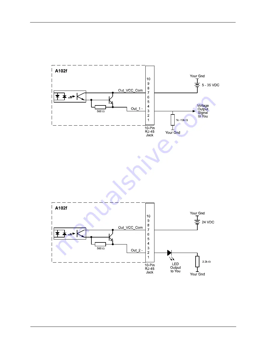
2.5.4 Typical Output Circuits
Figure 2-6 shows a typical circuit you can use to monitor an output port with a voltage signal. The
circuit in Figure 2-6 is monitoring camera output port 1.
Figure 2-6: Typical Voltage Output Circuit
Figure 2-7 shows a typical circuit you can use to monitor an output port with a LED or an
optocoupler. In this example, the voltage for the external circuit is 24 VDC. Current in the circuit is
limited to approximately 10 mA by an external 2.2k resistor. The circuit in Figure 2-7 is monitoring
camera output port 2.
Figure 2-7: Typical LED Output Signal
Summary of Contents for A102f
Page 1: ...USER S MANUAL Document Number DA00063006 Release Date 7 December 2010 ...
Page 4: ......
Page 25: ...Basic Operation Standard Features BASLER A102f 3 3 DRAFT Figure 3 2 Block Diagram ...
Page 62: ...Basic Operation Standard Features 3 40 BASLER A102f DRAFT ...
Page 166: ...Mechanical Considerations 7 6 BASLER A102f DRAFT ...


