Configuring the Camera
Basler IP Camera
45
3.8
Input / Output Parameters
The parameters in the
Input/Output
group are used to work with the camera’s digital input and
output pins and to configure the camera’s RS-232 serial port.
3.8.1
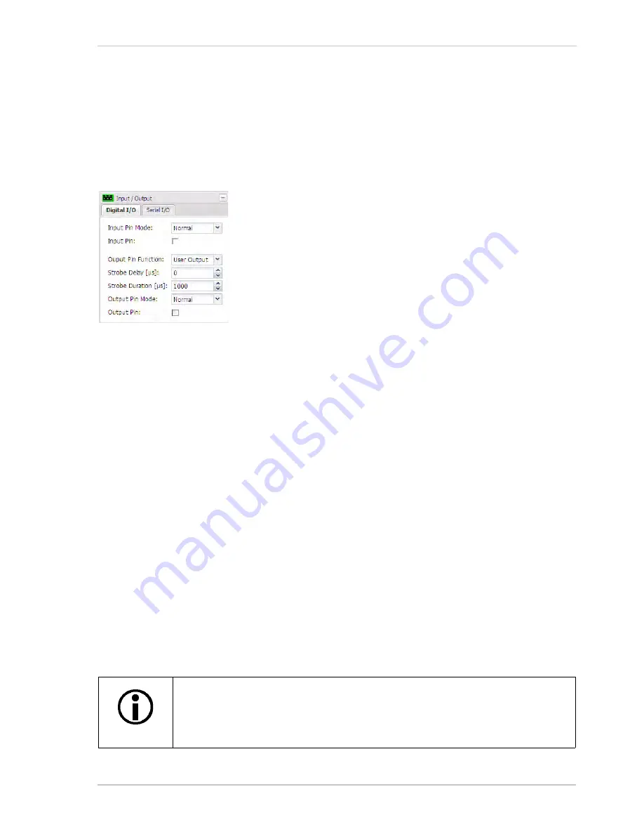
Digital I/O Tab
Input Pin Mode
- Sets whether the active/inactive state of the input
pin will operate normally or be inverted.
Normal
= The input pin will operate normally.
Inverted
= The operation of the input pin will be inverted.
See Table 3 on
page 66
for details about normal and inverted input
pin operation.
Input Pin
- Indicates the state of the camera’s digital input pin. If the
box is unchecked, the input is inactive. If the box is checked, the input
is active.
Output Pin Function
- sets the functionality of output pin 0 on the camera.
User Output
= The output pin state is user settable. You can set the state of the output pin by
using the
Output Pin
check box (see below).
IR Filter Announce
= The camera will announce the position of the IR-cut filter by setting the
state of output pin 0. See Section 6 on
page 71
for details about the IR-cut filter and the
announce feature.
Strobe
= The camera will output a pulse on output pin 0 that is synchronized to the start of each
image capture. This signal is useful for controlling things such as a strobe exposure lamp. The
Strobe Delay
and
Strobe Duration
parameters (see below) are used to adjust the characteristics
of the strobe pulse.
Strobe Delay
- If the
Output Pin Function
is set to
Strobe
(see above), the
Strobe Delay
parameter
sets a delay time (in microseconds) between when image capture starts and when the strobe pulse
becomes active.
Strobe Duration
- If the
Output Pin Function
is set to
Strobe
(see above), the
Strobe Duration
parameter sets the length of time (in microseconds) that the strobe pulse will remain active.
Output Pin Mode
- sets whether the active/inactive state of the output pin will operate normally or
be inverted.
Normal
= The output pin will operate normally.
Inverted
= The operation of the output pin will be inverted.
See Table 3 on
page 66
for details about normal and inverted output pin operation.
If the output pin has been set to the inverted mode and you restart the camera or
you power it off and back on, the output will be in the normal mode during the
camera bootup process and will return to the inverted mode once the bootup
process is complete.
Summary of Contents for BIP-1000c
Page 4: ...Table of Contents ii Basler IP Camera...
Page 8: ...Introduction 4 Basler IP Camera...
Page 10: ...Accessing the Camera 6 Basler IP Camera...
Page 66: ...Configuring the Camera 62 Basler IP Camera...
Page 68: ...Reset Tool 64 Basler IP Camera...
Page 74: ...The Terminal Connector 70 Basler IP Camera...
Page 80: ...Day Night Functionality 76 Basler IP Camera...
Page 86: ...Technical Specifications 82 Basler IP Camera...
Page 92: ...Revision History 88 Basler IP Camera...
Page 94: ...Feedback 90 Basler IP Camera...
Page 98: ...Index 94 Basler IP Camera white balance mask 22 white balance mode parameter 15...


