


FWG09I Assembly instructions
6
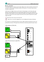
Direct connection
The FWG09 supplies an emergency power supply voltage of 5V (current is limited to 10mA) for the
connection of LED pictograms for alarm and voice communication. To do this, the LEDs must be
connected in position A-B.
Furthermore, the FWG09 also has a switch output for the pictograms, so that LEDs with higher
voltages can be supplied by means of an external power supply. This can be up to 60 volts; the
maximum current is 100mA. The switch output lies at position B-D; the negative terminal is always
switched. The ground of the power supply of the LEDs must be equal to the ground of the power
supply of the unit.
In current devices there is only one pin for ground!
Please do not connect the neighboring pin, as the FWG09 will be destroyed otherwise.
The pictograms start blinking alternately according to EN81-28:2018 if the battery is faulty or the
periodic calls can’t be sent. The exact cause of the error can then be queried in the service menu.


