background image

BARTINGTON INSTRUMENTS

DCN1040 

Page 15 of 39 OM3100/2

7.4. Connecting

The Grad-13 is connected to the Grad-13 battery box using the cable supplied. Connect power 
supply to the mains adaptor panel socket located on the front of the unit using the cable 
provided. 

7.5. Connecting Custom Systems

A data protocol DP2629 can be provided if the Grad-13 is to be powered by and connected to a 
custom system. Please contact Bartington Instruments for further information.

8. Operating Instructions

8.1. Operation

During operation, ensure that the battery box and cables are kept away from the gradiometer 
sensors.

Bartington Instruments supply a basic software, VisualGrad13, for communication with the Grad-
13. 

If the user wishes to expand upon this or create their own software, this is simplified by using 
the API which is documented in data protocol DP0105, available on request from Bartington 
Instruments. 

8.2. Visual Grad-13 Software Instructions

8.2.1. Installation

In order to connect the Grad-13 to a PC, an RS422 to USB/Ethernet converter is required. The 
converter used and tested by Bartington instruments is the ‘Brainboxes’ RS422 converter, and 
this will be refered to in this manual. However, there are many other commercially available 
converters that can also be used.

The installation requires Brainboxes (or other) device drivers as well as the Bartington Grad-13 
software. These need to be installed on a PC with a Windows OS. 

Firstly install brainboxes USB to Serial software (driver for RS422 converter) before installing the 
Grad 13 software.

Summary of Contents for Grad-13 Series

Page 1: ...Operation Manual for Grad 13 Digital Three Axis Magnetic Gradiometer...

Page 2: ...Functional Description 7 5 2 The Battery Box Front Panel 7 5 3 Power Supply 8 6 The Grad 13 8 Port Multiplexing Box 9 6 1 Functional Description 10 6 2 The 8 Port Multiplexing Box Front Panel 10 6 3...

Page 3: ...TRUMENTS DCN1040 Page 3 of 39 OM3100 2 10 Servicing Maintenance 37 11 End of Life Disposal 37 11 1 Waste Electrical and Electronic Equipment WEEE Regulations 37 Appendix A Guidance for Connection to M...

Page 4: ...ich serious bodily injury or death could result if the warning is ignored Caution Indicates a situation in which bodily injury or damage to your instrument or both could result if the caution is ignor...

Page 5: ...4 Three axis sensing magnetometer Note Refer to the outline drawing DR3344 on the product webpage for further information The magnetometer assembly is supported on shock resistant mounts inside an ele...

Page 6: ...ation 3 2 2 Grad 13 Multiplexing Box The Grad 13 Multiplexing Box converts the signal from the Grad 13 to ethernet output It is designed to be used with up eight gradiometers See Section 6 Grad 13 8 P...

Page 7: ...to USB A rechargeable battery is built into the box and a dedicated charger is provided with the unit A dedicated USB cable is also provided to provide connectivity to a computer 5 2 The Battery Box...

Page 8: ...en the battery is around 80 discharged The length of time taken to discharge to this level depends upon the number of gradiometers connected the battery age and the battery temperature WARNING The mai...

Page 9: ...e charger will switch to standby mode when the battery has reached full charge 6 The Grad 13 8 Port Multiplexing Box This section describes the installation and operation of the Grad 13 8 Port Multipl...

Page 10: ...e system is connected to a network The Low Power LED flashes to indicate that the battery is nearing the end of its charge Battery life remaining after this point is dependent upon the number of gradi...

Page 11: ...on 4 3 2 Charging for further information 5 Status Network and Low Power LEDs The Status LED indicates that the internal Brainbox is enabled The Network LED indicates that the system is connected to a...

Page 12: ...must be charged with the supplied charger only Non approved chargers will cause permanent damage to the batteries It could also affect the safety of users damage the equipment and invalidate the terms...

Page 13: ...Lights up when the charger cable is connected and powered It will show as RED during charging and GREEN when charging is complete WARNING The charger must be switched off before connecting to and disc...

Page 14: ...he device must be returned to Bartington Instruments for repair 7 Installation of the Grad 13 7 1 Unpacking Safe handling precautions must be observed 7 2 Orientation The directions of the sensor axes...

Page 15: ...munication with the Grad 13 If the user wishes to expand upon this or create their own software this is simplified by using the API which is documented in data protocol DP0105 available on request fro...

Page 16: ...control panel before installing this software Run the Grad13Install exe andfollow the instructions Once this has been completed it will create three shortcuts on your desktop VisualGrad13 Main Grad 13...

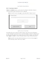
Page 17: ...ct Figure 8 The Connect to a Grad 13 Window This window allows you to connect to a Grad 13 device if the connection has already been correctly configured All connections that are currently available a...

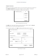
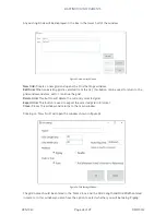
Page 18: ...nnect to a Grad 13 window to set up your connections Clicking on this will display the window shown in Figure 9 Figure 9 The Manage Grad Connections Window The Edit button can be used to edit any exis...

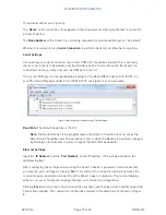
Page 19: ...re 11 Identifying the correct port using Device Manager Baud Rate The default baud rate is 115200 Note The Baud Rate has to be programmed in the Grad 13 therefore in most cases the default rate should...

Page 20: ...13 Note Connections can fail if the Grad 13 device is not connected connected to the wrong connection not powered or incorrectly configured This will lead to an error message when attempting to conne...

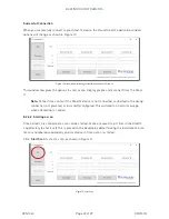
Page 21: ...stored within the pct scan file and may be refered to later this window is shown in Figure 14 Figure 14 Scan Notes Click on Start Scan to begin Once Start Scan is clicked data from the Grad 13 device...

Page 22: ...do so without affecting the data that is gathered from the Grad 13 device This is intended functionality of the software and exists to safeguard and favour the data stored to file instead of the scree...

Page 23: ...ta but not the recorded values until they are exported to Excel The three tickboxes Display Reference Graph Display Sensing Graph and Display Gradient Graph can be selected so that the graphs will be...

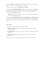
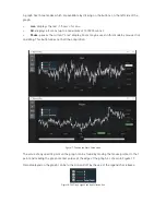
Page 24: ...used in this mode by mouse click and drag This button does not halt the acquisition Figure 17 The Live and Pause Graph views The value of any specific point on the graph can be found by moving the mou...

Page 25: ...export the data to Microsoft Excel csv format and will open it in Excel if it is installed The file will be stored in the same folder as the pct file specified in the File location see Figure 19 If ca...

Page 26: ...that is used during processing Once a file is opened information regarding the scan is displayed It is not uncommon that a small number of errors may exist you should note that the Data Process appli...

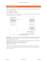
Page 27: ...a new survey and opens the New Survey Window see figure 23 Edit Survey Used to edit or view an existing survey Select the survey from the centre window and then use this button to open it Options All...

Page 28: ...the grid window and view edit or continue the grid Delete Grid This button will delete the currently selected grid Export Grid This button is used to export the selected grid in X format Close Closes...

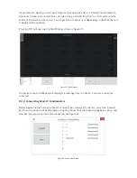
Page 29: ...shed Pressing OK will open up the Grid Window shown in figure 25 Figure 25 Grid Window The graph in the Grid Window will display the readings from the Grad 13 sensors as they are collected 8 3 2 Conne...

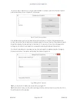
Page 30: ...on The window in figure 26 will then display Connected next to the Grad 13 if successful If an error is displayed the settings for this Grad 13 will need to be reviewed by selecting Configure Connecti...

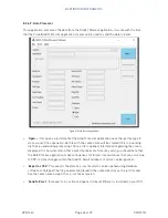
Page 31: ...Position to reference m This is the position of the Grad 13 in relation to the left hand sensor For example the most left hand sensor would be in position X 0 Y 0 Z 0 Coverage Width m This is the hori...

Page 32: ...abelled on the box Once the connection settings have been input clicking Test will attempt to connect to the Grad 13 and inform you whether it has been successful Click Save to save the settings Once...

Page 33: ...o not offset data will be displayed as recorded directly from the Grad 13 no offset will be applied selected by default Offset to fixed value per Grad Will add a fixed value offset to each Grad 13 whe...

Page 34: ...ws you to set the walking speed for data acquisition purposes The software will acquire data based on this speed and the size of grid entered so it is important that this is accurate Follow the instru...

Page 35: ...d 13 array can be repositioned before pressing start for the next traverse The current number of lines walked is listed in the top right hand corner of the screen Each number represents one traverse w...

Page 36: ...ines and indicate which direction they were taken in An example file with one Grad13 and one line is shown below SurveyMethod 0 PushPull 0 MetersPerSec 0 952380952380952 GradConfigSaved True Lines 1 2...

Page 37: ...cleaning the Grad 13 8 port multiplexing box the connector covers must be in place to avoid ingress of water to the pins 11 End of Life Disposal This product should not be disposed of in domestic or m...

Page 38: ...A trip current This must comply with local regulations 2 The mains input connectors are as follows Device Input Connector Mating Cable Connector 8 Way Multiplexing Box IEC C14 IEC C13 Battery Box IEC...

Page 39: ...ton Instruments Limited in the following countries United Kingdom Australia Brazil Canada China European Union India Japan Norway and the United States of America Bartington Instruments Limited 5 Thor...

Reviews: