Lindsay Transportation Solutions Sales and Services, Inc
(888) 800-3691 [U.S. toll free] or +1 (707) 374-6800
Lindsay Transportation Solutions Sales and Services, Inc
(888) 800-3691 [U.S. toll free] or +1 (707) 374-6800
14
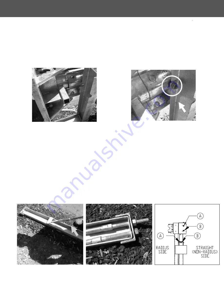
Figure 17. Attach Impact Head to rail 1.
Step 9 – Attach Impact Head
Place Impact Head on upstream end of rail 1 and attach using 8 standard splice bolts with nuts on
traffic face (Figure 17).
Hint
: Place bottom two bolts first then use guardrail pin bar to lever head
up snug onto rail.
Bolt head and rail 1 to post 1 using the supplied M16 x 50mm (5/8 in x 2 in) guardrail post bolt.
Ensure to use a 5/8” hex nut at post 1.
Use a 50mm x 50mm (2 in x 2 in) washer under the nut
on the inside of post 1 (Figure 18).
Step 10 – Place the Cables
Push the cables under the steel strap on the Ground Strut (Figure 19) and forward through the
holes at the top of the anchor. Lay the cables out parallel to the guardrail, downstream from the
anchor.
Ensure that bottom cable (Cable B in Diagram 1) has half the thread protruding through the an-
chor, as shown. Ensure the top cable has the nut wound on a least two turns past the end of the
thread (Figure 20). Cable A should always pass through the top hole on the impact head. Cable
B should always pass through the bottom hole on the impact head as shown in Diagram 1.
In addition, ensure that the bottom cable passes through the ground strut hole nearest the straight
(non-radius) side of the system.
Figure 20. Thread the nuts as shown.
Figure 19. Push cables under steel strap on
Ground Strut.
Diagram 1.
Figure 18. Bolt head and rail 1 to post 1 with
washer & 5/8” hex nut.
INSTALLATION AND MAINTENANCE MANUAL


