background image

24

24

 25

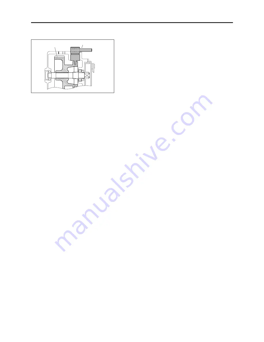
*  Make  sure  that  the  changeover  clutch  lever  is  fitted 

tightly into the groove of the #7 gear.

  Apply  enough  grease  to  the  gear  tooth  surface  and 

bearings when assembling them.

5) Before attaching the cover, verify the gears’ movement 

and  the  number  of  the  washers.  If  the  cover  doesn’t 
fit well, the direction of the gears may be wrong or the 
gears may not be fitted well. 

*  Please refer to the Parts Catalog as well. 
*  Please do not force the cover to fit by hitting on it. Such 

actions could cause a fracture or dent. 

*  When  tightening  the  bolts  on  the  cover,  first  tighten 

them by hand, and then using a tool, tighten them grad-
ually in a diagonal order (over a couple of  rounds).

  After the bolts are tightened, turn the drum by hand to 

see if it turns smoothly.

#7 gear

Changeover clutch lever

Summary of Contents for LM18G Series

Page 1: ...Ver 1 3...

Page 2: ...or disassembling and maintaining engine and other parts that are specifically to be repaired by the manufacturer Please contact the dealer where you purchased the product or Kyoeisha USA for a repair...

Page 3: ...g installing the drum assembly 26 8 Disassembling assembling the drum 28 9 Removing installing disassembling assembling the transmission shaft 30 10 Disassembling assembling adjusting the engine clutc...

Page 4: ...01kg 22 in 55 6cm 18 in 45 6cm 26 in 64 6cm Mowing width Reel diameter Speed km h 5 04 in 12 8cm Number of reel blades Cutting height min max 0 08 in 1 14 in 2 0mm 28 5mm Mowing weight Mowing section...

Page 5: ...shaft of the right and left gears and the intermediate shaft of the groomer Periodically fill up the grease nipples with approx 1 g of grease EXCELITE EP No 2 one or two times with a compact manual gr...

Page 6: ...light Is the sliding of the cam bush and frame extremely unsmooth Adjust the compression length of the spring 1 8 to 50mm Lightly engage the blades Adjust light contact to reel and Bedknife NO NO NO...

Page 7: ...frame rattle together Replace the cam bush Replace the frame YES NO Is the spring pressure of the adjusting lever too light Clean and apply grease to the sliding sections to make the sliding smoother...

Page 8: ...traight roller Are the bedknife and mowing height adjusted appropriately Refer to Section 5 13 Setting the mowing height gauge and blade thickness in the Owner s Manual Change the mowing height Replac...

Page 9: ...s down enough remove the build up Do not touch the muffler and engine either during or right after operation as those areas can be dangerously hot This could cause burns Always keep clean the safety s...

Page 10: ...Place the mower on a stable workbench and lower the handle 3 Always set the change lever located at the top of the left frame to the Travel ON position in order to keep the mower from moving 4 Engage...

Page 11: ...ng the reel cover Models equipped with a groomer 8 Unscrew the tall nuts 8 58 on both sides and the right case locking bolt 8 60 and then remove the groomer Ass y Lower the entire groomer Ass y and th...

Page 12: ...fe base Please keep 1 5 pieces of 0 4SPCC washer1220 for clearance adjustment between the fulcrum seat 1 5 and the frame 6 32 43 if there are any of them 12 While supporting the bedknife base COMP rem...

Page 13: ...t illustration lightly with a wooden hammer 17 Remove the washer 6 52 53 36 tooth reel gear and 36 tooth 45 tooth reel gear 6 54 33 tooth reel gear and 42 tooth reel gear 1 46 18 Remove the reel gear...

Page 14: ...5 3 2 compression spring 26 922 2SPCC washer 1635 Cover Models not equipped with a groomer Remove the bolt and nut and detach the cover 1 28 Remove the two left nuts 1 32 washer 1 34 and spring 1 35...

Page 15: ...ing 1 36 on both sides 21 Unscrew the three 8 hexagon socket head flush bolt 20 1 37 from the right frame using an Allen wrench 5 mm 22 While supporting the reel cutter push the right reel housing 1 5...

Page 16: ...core 1 36 by hammering a flat head screwdriver into it Since the outer bearing is not pressed fit you can re move it smoothly by keeping it parallel to the housing as you pull it out 5 Prepare the oi...

Page 17: ...o the housing 8 Hammer the oil seal 1 38 from the inside 9 Hammer the tapered bearing core 1 36 from the out side Please make sure that the outer bearing is going in parallel to the housing 10 Install...

Page 18: ...rings 1 36 to the reel cut ter and make sure the tapered side faces in 15 Install the left bearing collar 1 43 to the reel shaft and after matching the holes on the collar and shaft insert the needle...

Page 19: ...just the length of the spring to 11 5mm while loosening the 20 tooth reel gear and secure it using the reel gear securing nut 8 45 They are left hand threaded Models not equipped with a groomer Tighte...

Page 20: ...e frame 1 Insert the bedknife base arm 1 11 into the bed knife base 2 Temporarily secure the bedknife base arm with the fulcrum seat bolt 1 4 3 Secure it tightly with the bolt 1 25 under the bedknife...

Page 21: ...dangerous 6 Adjust the position of the cam bush 1 22 so that a newspaper is cut smoothly at both ends of the reel When cutting a newspaper insert it vertically to the bedknife Turn the reel cutter sl...

Page 22: ...screw 1 12 10 Tighten the lock nut 1 21 on the cutter pin on both sides Make sure that the cam bush 1 22 doesn t move from the marked position Blade engagement 1 When the blade adjusting nut 1 1 is t...

Page 23: ...ttach the 10 special bolt 35 1 47 Lock the reel by inserting a wooden hammer handle into the reel cutter to prevent the reel from turning Left cover Bolt 6 94 Bolt 6 30 Bolt 6 2 Reel cutter 10 special...

Page 24: ...and secure it temporarily with the spring washer 8 59 and tall nut 8 58 4 Attach the right case locking bolt 8 60 This bolt is for keeping the case from unfastening not for locking it down Be careful...

Page 25: ...with the two bolts 1 25 Bolt x 2 left right Reel cover Reel cover Bedknife base Bolt 4 Installation of the reel cover Cover Models not equipped with a groomer Attach the cover After making sure that...

Page 26: ...22 23 bearing 6 24 and collar 6 25 from the outer drum shaft If you mark the gears with numbers as shown in the illustration using a permanent marker before you re move them it helps to make the direc...

Page 27: ...well the direction of the gears may be wrong or the gears may not be fitted well Please refer to the Parts Catalog as well Please do not force the cover to fit by hitting on it Such actions could caus...

Page 28: ...23 bearing 6 24 and collar 6 25 from the outer drum shaft Remove the gears in the order of the numbers shown in the illustration When removing the 2 gear be careful not to lose the key Pay attention t...

Page 29: ...4 Remove the 1 and 2 gears 5 Remove both the right and left packings Be careful not to break the packings when removing them If they ever break exchange them with the new ones Unscrew the three bolts...

Page 30: ...the stand 9 Assemble the corresponding parts in the reverse order that they were disassembled When assembling them apply enough grease to the gear tooth surface and bearings When installing the drum...

Page 31: ...rum and remove one of them If an adjustment shim is used be careful not to lose it 3 Pull out the intermediate drum shaft 4 24 34 40 Be careful not to lose the drum center collar 4 Tap inside the drum...

Page 32: ...from inside Do not forget to insert the drum center collar 8 Place the stop ring 4 17 on both sides If an adjustment shim was used do not forget to replace it 9 Secure the outer drum shaft with four b...

Page 33: ...t and then remove the traveling wheels on both sides 2 Open the clutch cover and remove the clutch cover re ceiver 5 43 44 53 Remove the two bolts 3 Remove the six bolts 6 2 six bolts 6 30 one bolt 6...

Page 34: ...d Remove the 1 gear 8 Keep the right transmission shaft 6 13 from turning by using something like pliers and remove the 3 gear by turning it clockwise Remove the stop ring 6 34 on the right side first...

Page 35: ...it out by hand remove it by tapping it lightly with a wooden hammer Check for any wear and damage on the oil seal bear ing and shaft and if necessary replace them When replacing them pay attention to...

Page 36: ...the gear by turning it all the way to the left and then turn it back to the right a quarter of a circle left hand threaded Then secure it with the lock nut 6 6 To avoid overstretching the transmission...

Page 37: ...gear 5 39 and 1 shaft collar 5 38 3 Unscrew the four bolts 5 18 and remove the clutch box 5 16 4 Remove the four bolts 7 1 from the engine Do not remove the four bolts 7 4 from the engine base 5 Remov...

Page 38: ...acing 5 31 When replacing the facing make sure the direction is correct 9 Assemble the corresponding parts in the reverse order that they were disassembled up to assembly of the engine Make sure to in...

Page 39: ...his product adjust the clearance at 6 locations between the engine clutch and the clutch facing to 0 5 1 00mm 0 20 0 40in by hammering lightly with a tool such as a plastic hammer in the direction of...

Page 40: ...grease from the polished surface and the drum surface When necessary replace the brake shoe and packing with new ones 4 First set the brake shoe as shown in the right illustra tion of step 2 Make sure...

Page 41: ...k adjust it by tightening the adjusting nut of the brake wire Set the brake shoe so that it does not always touch the brake drum Avoid the brake always being engaged The brake may be engaged if when r...

Page 42: ...washer between the front roller and bracket 5 Remove left hard thread roller bolt Part K0071000152 6 First loosen the lock nut 2 26 and stopper bolt 2 25 and remove the roller bracket 2 24 on the lef...

Page 43: ...is sticking out more 9 Secure the removed front roller shaft on a vice and remove the bearing 2 14 15 from the shaft using a pulley remover 10 Remove the bearing on the opposite side by tapping the r...

Page 44: ...set on the outside of the roller The lip surface is inside the oil seal as shown in the illustra tion Have a stop ring 2 13 and washer 2 16 available Inspect each part such as the roller shaft and re...

Page 45: ...ter stepped section Insert the shaft from the end of the roller with no bear ing Place the roller shaft firmly into the bearing 7 After the shaft is inserted turn the roller upside down and insert the...

Page 46: ...Driving tool Oil seal 9 As shown in the illustration match the bracket to the frame s joint and set the top of the bracket in the groove of the roller adjuster 2 21 10 Insert the washer 2 8 between t...

Page 47: ...of the roller shaft 13 Disassembling assembling the front roller without a groomer Hollow set Square root bolt Washer Disc spring Tall nut 12 Secure the roller with the tall nut 2 1 disc spring washer...

Page 48: ...sing 8 63 3 Pay attention to the direction of the oil seal 8 27 Disassemble assemble adjust and replace Before assembling them apply grease to the lip sur face of the oil seal 4 Remove the clutch reta...

Page 49: ...order and direction of the oil seal 8 16 and bearing 8 34 9 Replace other parts when necessary Pay attention to the parts such as gear which need to be set in a certain direction 20 tooth vertical ge...

Page 50: ...nut Groomer Blade Locking nut 8 76 is attached on the spline side of the vertical shaft If it is attached stand the shaft with the spline side on the bottom 2 First insert the two collars 8 22 and th...

Page 51: ...the needle bearings before installing the cover Refer to the Parts Catalog 5 Install the left vertical housing 8 63 Please refer to 1 5 of Equipped with the groom er section on page 21 for installing...

Page 52: ...92 2 Raise the catcher arm and remove it from the mower 3 Unfasten the bolts 13 15 of both side of the catcher arm To prevent roller shaft from spinning slide a screw driver through the hole of the r...

Page 53: ...h is sticking out more 6 Secure the removed front roller shaft on a vice and remove the bearing 13 19 20 from the shaft using a pulley remover 7 Remove the bearing on the opposite side by tapping the...

Page 54: ...et on the outside of the roller The lip surface is inside the oil seal as shown in the illustra tion Have a stop ring 13 21 and washer 13 18 available Inspect each part such as the roller shaft and re...

Page 55: ...roller shaft Insert the shaft from the end of the roller with no bear ing Place the roller shaft firmly into the bearing 7 After the shaft is inserted turn the roller upside down and insert the washer...

Page 56: ...er through the hole of the roller shaft and hold for support while tight ening bolt 13 15 10 From the front of the greens mower drop the catcher arm into the right position 11 Slide washer 13 11 over...

Page 57: ...ed space between the arm stopper and stopper brackets 13 6 8 should be 1 mm when the front roller 3 37 is parallel with the roller 13 23 of catcher arm 2 Lock the arm stopper 13 5 into desired positio...

Page 58: ...55 19 Reference Bl Bl Black Bu Blue W White Bl Bl Bu W or Bu W 1 2 3 1 ENGINE SWITCH 2 SPARK PLUG 3 IGNITION COIL 4 5 6 4 COIL ASSY LAMP 5 HEADLIGHT SWITCH 6 HEADLIGHT Wiring Diagrams GX120...

Page 59: ...56...

Page 60: ...LM56GA SM USZ 09M 00 SPEC...

Reviews: