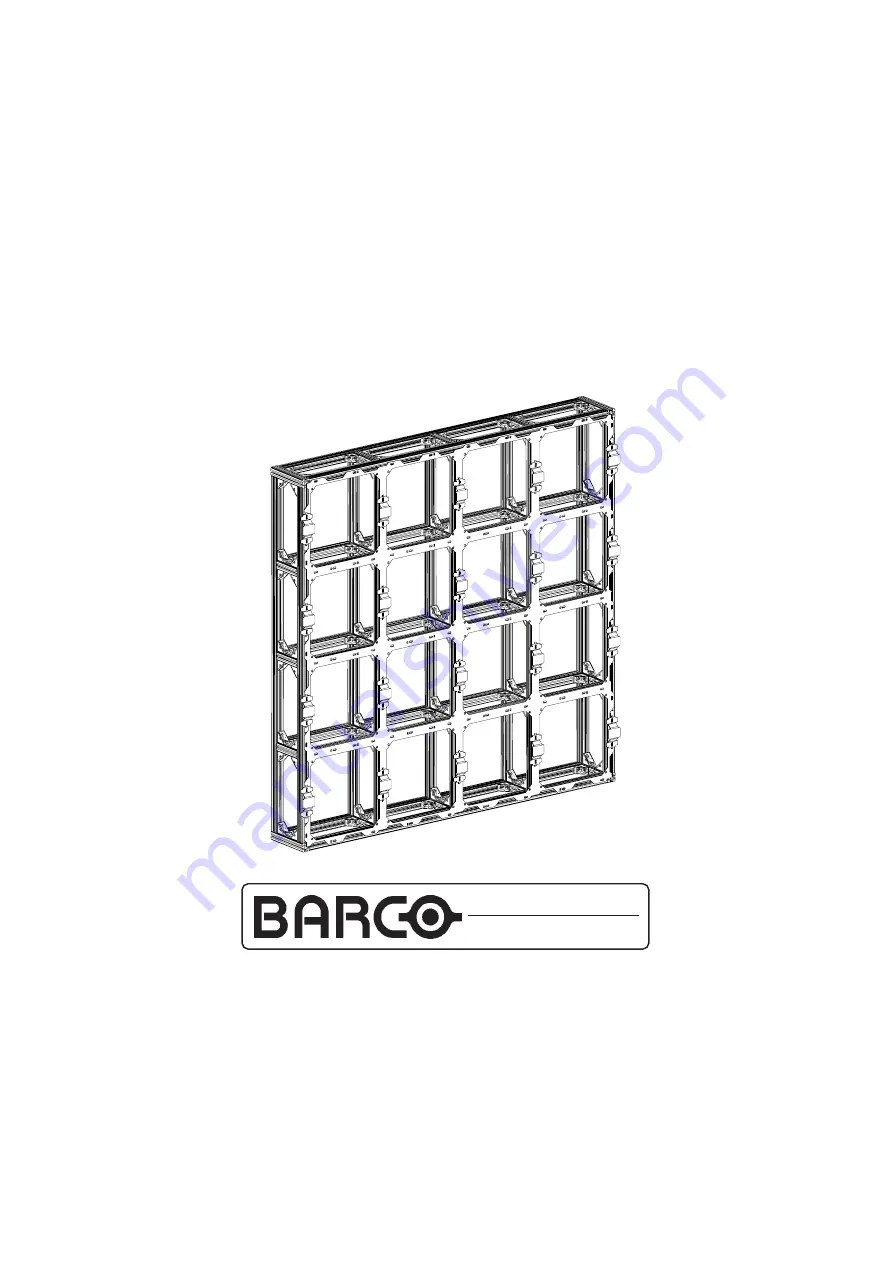
INSTALLATION MANUAL
Screen Assemby Blocks
3x3 (R9850010)
4x3 (R9850020)
4x4 (R9850030)
Day Light
Displays
DAY LIGHT DISPLAY SYSTEMS
Page 1: ...INSTALLATION MANUAL Screen Assemby Blocks 3x3 R9850010 4x3 R9850020 4x4 R9850030 Day Light Displays DAY LIGHT DISPLAY SYSTEMS ...
Page 2: ...e Trademarks are the rights of their respective owners All rights reserved Produced by BARCO NV 19 06 2001 BARCOn v DaylightDisplaySystems Noordlaan 5 B 8520 Kuurne Belgium Tel 32 56 368828 Fax 32 56 368824 e mail sales bps barco com Visit Barco on the web http www barco com PrintedinBelgium ...
Page 3: ...Art No R5976076 Date 19 06 2001 INSTALLATION MANUAL Rev 03 Screen Assemby Blocks 3x3 R9850010 4x3 R9850020 4x4 R9850030 Day Light Displays DAY LIGHT DISPLAY SYSTEMS ...
Page 4: ......
Page 5: ...on 18 What has to be done 18 Necessary Tools 18 Disconnecting Left Sides 18 Connecting Side to Side 18 Disconnecting Bottom Side 19 Connecting Top to Bottom 19 Connecting Left Top 20 Image 1 Left side removed 21 Exploded Image1 21 Image 2 Right side Springs 22 Exploded Image 2 22 Image 3 Bottom side removed 23 Exploded Image 3 24 Image 4 Left bottom side removed 25 Exploded Image 4 26 Tile Mountin...
Page 6: ... R9004000 DLITE L5 P14 VGN7 G2 R9004005 DLITE L5 P14 VGN7 G2M R9004021 DLITE L5 P19 VGN10 G1 R9004020 DLITE L5 P19 VGN10 G2 R9004030 DLITEL5P28 R9004010 DLITEL5P28VGN14 R9004015 DLITE L5 P28 VGN14 M Order Numbers Ordering spare replacement parts R9850290 DLITEFRONTACCESS P14 R9850300 DLITEFRONTACCESS P19 R9850310 DLITEFRONTACCESS P28 R9850110 DLITEFLIGHT CASE BTM TOP R9850120 DLITEFLIGHT CASE 1 LA...
Page 7: ...ave any question regarding the safety of an application The manufacturer assumes no liability for incorrect inadequate irresponsible or unsafe assembly of systems Product Care Structural Mounting Components should be kept dry clean lubricated only if recommended coated properly and otherwise maintained in a manner consistent with part design BARCO products must be used in a manner consistent with ...
Page 8: ...her cables and connectors may result in risk of electric shock and risk of fire To protect against risk of fire by overloading of power cables MAXIMUM 6 TILES in one column may be connected in parallel Each source cable supplying a column of MAXIMUM 6 TILES should be protected by a circuit breaker or fuses rated 16 A 250 V Disconnect device When the appliance inlets of the individual tiles are not...
Page 9: ...rized or grounding type plugs sockets If the provided sockets plugs are damaged then replacement of the defective parts must be undertaken immediately Protect the power data cords from being walked on or pinched particularly at plugs convenience receptacles and the point where they exit from the apparatus Replace damaged power data cords immediately Only use attachments accessories specified by th...
Page 10: ...tal conditions 7 Location 8 Ground clearances 9 Ground stability 10 Local regulations regarding such installations Support structures must be assessed on an individual basis never construct a wall if there is uncertainty regarding the stability of an installation or the load holding capabilities Consult Barco for advise on professional rigging organizations if doubts on a systems viability are in ...
Page 11: ...other will form a good propriety step This manual describes a simple installation using four Assembly Blocks of size 3x4 Wall securing or supporting structures are not included Always assemble a wall flat on the ground and then raise to its vertical position dependent on the circumstances and facilities available Image 1 System block diagram Image 2 Assembly on floor System Overview Continued ...
Page 12: ... Viewing Angle minimum 50 brightness Horizontal 120 120 120 120 120 Vertical 60 60 60 60 60 Light Output at 6 500 K 6 500 Nit 6 500 Nit 7 000 Nit 6 500 Nit 7 000 Nit Individual LED corrected Wall calibrated 5 000 Nit 5 000 Nit 5 500 Nit 5 000 Nit 5 500 Nit Number of LED s LED s m 25 600 14 350 25 600 6 400 6 400 LED s ft 2 379 1 334 2 379 594 594 Power Consumption Watts m Maximum Full white specif...
Page 13: ...used to satisfy safety guidelines Necessary Tools Image 1 Power Source cable Cables Follow the guide For safety reasons it is not recommended to use any other parts than those specified above Power Source Cables emanate from the Power Box s R9850050 Power Linking cables connect from tile to tile Part Detail Article no Length Image Power Cables Source Cable Z349901 3 5 M 1 Linking Cable Z3499011 0 ...
Page 14: ...ystems Image 2 Power Data linking cables Power Linking Cable Data Linking Cable Image 3 Safety Cable Image 4 Caliber tool Caliber tool for Assembly Block alignment Cabling Caliber Continued Power Linking Cable Data Linking Cable ...
Page 15: ...his simple example scenario Preparation 1 2 3 1 1 1 To prepare the Wall firstly 1 2 is joined to 1 1 with the left side of 1 2 removed 2 1 is joined to 1 1 with the bottom side of 2 1 removed 2 2 is joined firstly to 1 2 then to 2 1 2 2 has its bottom and left side removed By the simple removal of the left side or bottom side or both left bottom sides of an Assembly Block any Wall size is possible...
Page 16: ... Safety Guidelines 1 2 3 Example 1 Example 1 1 2 3 4 Each Assembly Block is coded with two numbers The first number indicates the row in which to assemble the second indicates the column This code starts counting from the Assembly in the bottom left corner It s also important to make sure that every Assembly is assembled in the right direction so top up The basic connection joint consists of Alumi...
Page 17: ...en profiles Ensure no gap between the two profiles Image 3 sides of profiles Check if the sides of both profiles are in the same plane Image 4 angle between profiles Ensure the angle between profiles is 90º 90º Assembly Preparation Continued û ü û û ü ü ...
Page 18: ... Assembly Block will have to be removed dependent on its location in the complete Wall Assembly If sides need to be detached these are either the left or bottom side or both left side bottom but never top or right 1 2 1 1 Undo and remove only the Hammer Bolts in Aluminum Corners that secure the left side frame Remove the left side from the Assembly Block Step Action Image 1 2 3 4 5 6 Example 2 2 2...
Page 19: ...ove Bottom side frame from the Assembly Block Step Action Image 1 2 3 4 5 6 Example 3 Example There is no left side to remove from Assembly 1 1 or 2 1 From Assembly 2 1 removal of the bottom side is necessary as explained above Place the Assemblies against each other Put at least two calibers in the holes on the connection of the two Assemblies to make sure that there isn t any displacement of the...
Page 20: ... both other joining Assemblies Therefore a shift of the aluminum corners on one side left or bottom of the Assembly will be required For Assembly 2 2 the aluminum corners on the left side of the Assembly are shifted about three centimeters to the right the same for all corners on that side After connection of the bottom side you can replace the corners on the left side to their original position T...
Page 21: ...RCO 21 Daylight Display Systems Image 1 Left side removed The Left side removed from a Assembly Block See Exploded Image1 To be continued on next page CompleteAssembly Exploded Image1 Dislocation corners ...
Page 22: ...aylight Display Systems Right side Springs See Exploded Image 2 To be continued on next page CompleteAssembly Image 2 Right side Springs Exploded Image 2 Caliber holes Assembly Connection Continued Caliber holes ...
Page 23: ...RCO 23 Daylight Display Systems Image 3 Bottom side removed The Bottom side removed from an Assembly Block To be continued on next page See Exploded Image 3 CompleteAssembly Assembly Connection Continued ...
Page 24: ...BARCO 24 Daylight Display Systems Dislocation corners Caliber Holes Exploded Image 3 To be continued on next page Assembly Connection Continued ...
Page 25: ...Daylight Display Systems Image 4 Left bottom side removed The left side Bottom side removed from an Assembly Block To be continued on next page CompleteAssembly See Exploded Image 4 Assembly Connection Continued ...
Page 26: ...BARCO 26 Daylight Display Systems Exploded Image 4 Assembly Connection Continued Shift Corners 3cm to the Right Caliber Holes Caliber Holes ...
Page 27: ... 4 1 1 2 2 3 Ensure the tile is in the right position so top up Ensure the tiles positioning pins are in the corresponding holes of the Assembly Click the tile into the Assembly until the tiles spring latches are totally hooked behind the plates of the Assembly Connect a safety cable from each tile to the Assembly Loop through the upper handle on the back of a tile and around a frame member Ensure...
Page 28: ...BARCO 28 Daylight Display Systems Exploded Views 2 Tile Mounting Points Image 2 Tile Mounting See Exploded Views 2 Positioning pin Spring latch Tile Mounting Continued ...
Page 29: ...fety cable A Safety Cable is attached to each and every tile in the wall Loop through the upper handle on the back of a tile and around a frame member Ensure to clasp the two ends of the safety cable together Tile Mounting Continued safety cable ...
Page 30: ... OUT plus DATA IN and DATA OUT These must be connected correctly for proper operation Important ensure a Safety Cable is securing each and every tile on the wall before attempting to connect Power and Data Cables Necessary Tools 1 1 There are four connection ports on the back of each tile The POWER IN and OUT and the DATA IN and OUT These must be connected correctly for safe operation Step Action ...
Page 31: ...long Source Power Cable for each column of six tiles in the display The Source Power Cable has to be connected with the lowest tile power in socket of the column and the other end is plugged into the Power Box A maximum of 6 six tiles can be connected to each other via one source cable For greater display sizes more than one source cable for each column containing more than six tiles is required A...
Page 32: ... DATA OUT IN POWER DATA OUT IN POWER DATA OUT IN POWER DATA OUT IN POWER DATA OUT IN daisy chained to maximum 6 tiles per branch POWER DATA OUT IN POWER BOX POWER DATA OUT IN COMPLETE DISPLAY NOT SHOWN ONLY THE PRINCIPLE IS DEMONSTRATED Image 2 Power linking Source cables to a maximum of six tiles per column Power Connections Continued ADHERE TO SAFETY GUIDE LINES ...
Page 33: ...e the data linking of the tiles either in the horizontal or vertical directions Always start the linking with the first tile of the display the tile that is connected with the digitizer This first tile can be any tile in a corner The data cable coming from the digitizer is connected to the DATA IN of the first tile daisy chain the data linking cables from the DATA OUT of one tile to the DATA IN of...
Page 34: ...N POWER DATA OUT IN POWER DATA OUT IN POWER DATA OUT IN POWER DATA OUT IN DIGITIZER TO DISPLAY daisy chained to all tiles COMPLETE DISPLAY NOT SHOWN ONLY THE PRINCIPLE IS DEMONSTRATED LAST TILE WILL BE IN A CORNER FIRST TILE MAY BE IN ANY CORNER Image 1 Data linking Data linking to ALL tiles in a wall vertically realized Data Connections Continued ADHERE TO SAFETY GUIDE LINES ...
Page 35: ...ot recommended to use any other parts than those specified Trim Mounting To place Trim around the Wall follow the next procedure 1 2 1 Trims can easily be attached to the display wall by just bolting to the Assembly Edges They can also be bolted to each other In this way you can also fasten the trim in the top corners of the display Step Action Image Image 1 Trim around Wall Trim ...
Page 36: ...t as well as from the back as described above This can be realized by unscrewing it and disconnecting the inside power and data cable Now you can install another tile by placing this connection module into it and placing the tile into the Assembly again Step Action Image continued on next page 1 2 2 Put the Front Accessing Tools into the little holes in the sides of the tile Vertically in the midd...
Page 37: ...Display Systems Image 2 Front Access Front Access Tile Accessing Continued Image 1 Back Access Back Access Extract by nudging forward twisting diagonally and pulling back through Access Tools ADHERE TO SAFETY GUIDE LINES ...
Page 38: ...e Image 1 Front Digitizer Image 2 Back Digitizer 1 2 1 2 1 2 The Digitizer is connected with the first tile of the display This first tile can be any tile in a corner of the display Connect the DATA IN port of this first tile of the Display with the Digitizer utilizing an appropriate Data cable Plug this cable into the back of the Digitizer into the TO DISPLAY port Step Action Image RS232 from PC ...
Page 39: ... the Digitizer the Power Box s the P C and the Display All should be interconnected appropriately Necessary Tools Connections To connect the complete system follow the next procedure 1 2 3 4 1 Connect the correct data cable from the TO DISPLAY output on the rear of the Digitizer with the DATA IN of the chosen corner tile of the Display Connect the RS232 OUT output from the P C to the RS232 IN on t...